rusEFI project
Advanced
Boost Control
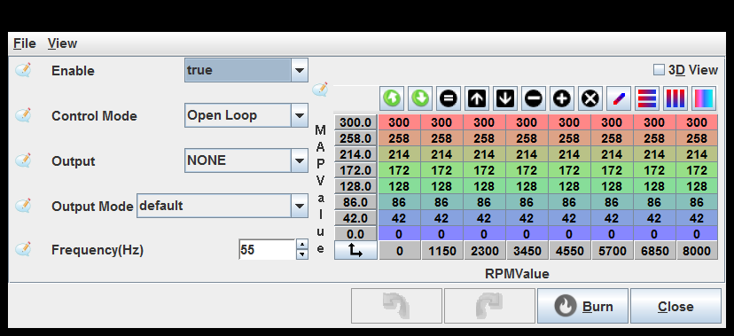
General Purpose PWM 1

Pin: This implementation produces one pulse per engine cycle. See also dizzySparkOutputPin.
On above duty(%): In on-off mode, turn the output on when the table value is above this duty.
Off below duty(%): In on-off mode, turn the output off when the table value is below this duty.
Duty if error(%): If an error (with a sensor, etc) is detected, this value is used instead of reading from the table. This should be a safe value for whatever hardware is connected to prevent damage.
Load Axis: Selects the load axis to use for the table.
General Purpose PWM 2

Pin: This implementation produces one pulse per engine cycle. See also dizzySparkOutputPin.
On above duty(%): In on-off mode, turn the output on when the table value is above this duty.
Off below duty(%): In on-off mode, turn the output off when the table value is below this duty.
Duty if error(%): If an error (with a sensor, etc) is detected, this value is used instead of reading from the table. This should be a safe value for whatever hardware is connected to prevent damage.
Load Axis: Selects the load axis to use for the table.
General Purpose PWM 3

Pin: This implementation produces one pulse per engine cycle. See also dizzySparkOutputPin.
On above duty(%): In on-off mode, turn the output on when the table value is above this duty.
Off below duty(%): In on-off mode, turn the output off when the table value is below this duty.
Duty if error(%): If an error (with a sensor, etc) is detected, this value is used instead of reading from the table. This should be a safe value for whatever hardware is connected to prevent damage.
Load Axis: Selects the load axis to use for the table.
General Purpose PWM 4
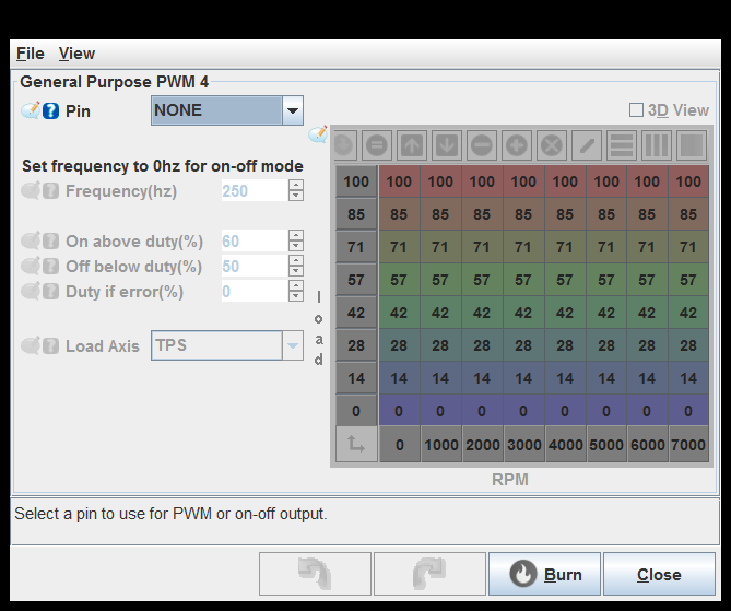
Pin: This implementation produces one pulse per engine cycle. See also dizzySparkOutputPin.
On above duty(%): In on-off mode, turn the output on when the table value is above this duty.
Off below duty(%): In on-off mode, turn the output off when the table value is below this duty.
Duty if error(%): If an error (with a sensor, etc) is detected, this value is used instead of reading from the table. This should be a safe value for whatever hardware is connected to prevent damage.
Load Axis: Selects the load axis to use for the table.
FSIO inputs

Aux PID
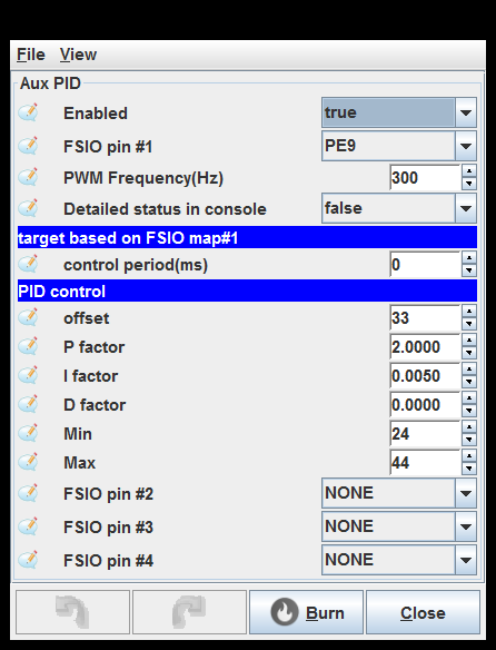
Detailed status in console: Print details into rusEfi console
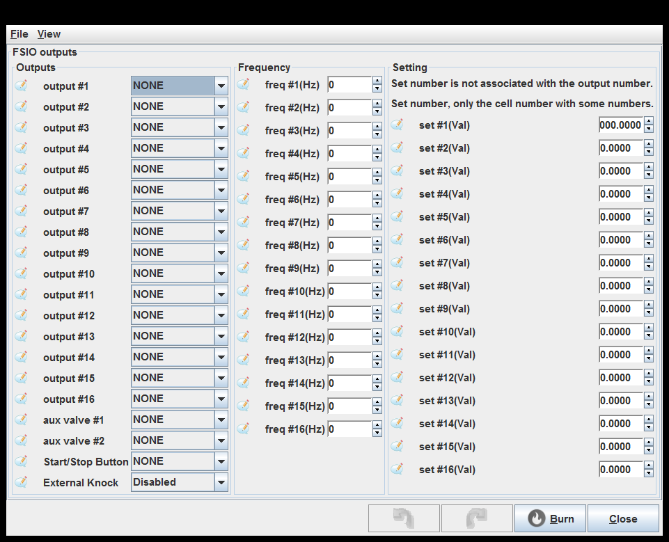
FSIO outputs
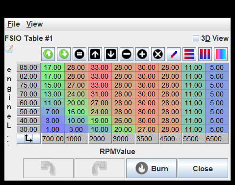
FSIO Table #1
FSIO Table #2

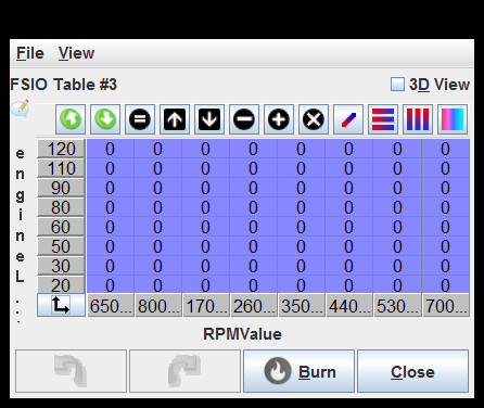
FSIO Table #3
FSIO Table #4

FSIO Formulas
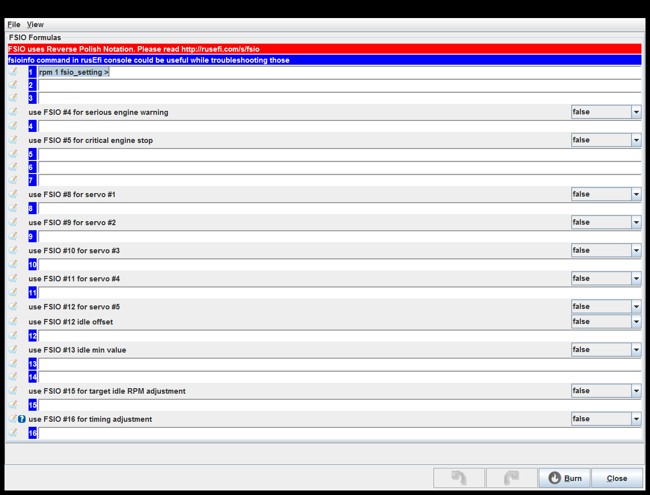
use FSIO #16 for timing adjustment: See fsioTimingAdjustment
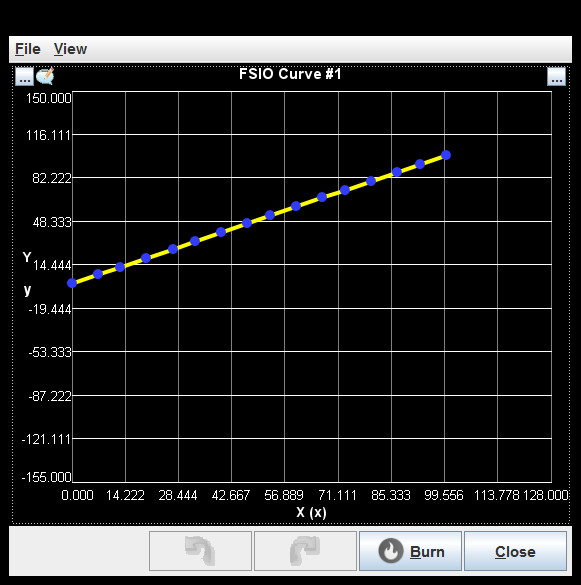
FSIO Curve #1
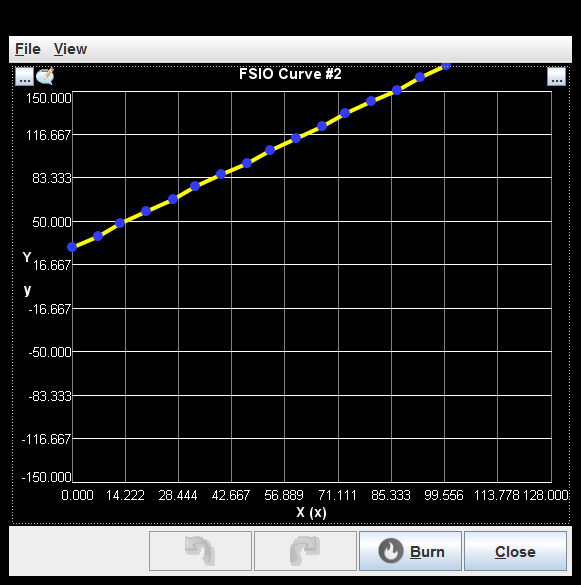
FSIO Curve #2
FSIO Curve #3

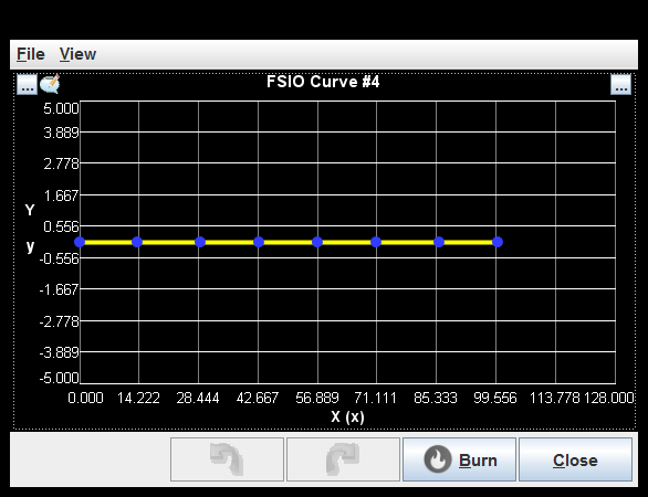
FSIO Curve #4
generated by class com.rusefi.MdGenerator on Fri May 01 15:24:28 EDT 2020