Trigger Configuration Guide
Hall Effect Sensors
**note: the hall effect section also includes optical sensors, as they behave electrically the same as hall sensors**
Wiring
Hall sensors are easy to wire, as they have no polarity. Simply connect the sensor's signal wire to any digital input on your ECU. Connect the ground pin to a sensor ground on the ECU, and the power supply pin (if present) to either a 5v sensor supply pin, or a switched 12v source. Consult your factory wiring diagram (or check with a multimeter on the stock ECU) to determine whether your sensor needs a 5v or 12v supply voltage. Most sensors operate at 5v.
Some sensors require a pullup resistor on the signal line (because they have an open collector output), but rusEFI ECU digital inputs include an internal pullup resistor that should be sufficient for any hall cam/crank position sensor.
VR (variable reluctance) Sensors
Wiring
VR sensors have two wires, VR+ and VR-, usually with an additional shield that protects these two wires from external noise (mostly from the ignition system). Connect one wire to the VR+ input, and the other to the VR- input. Unfortunately, there is no hard-and-fast standard across manufacturers about which wire is called + and which -, so you essentially have to make an educated guess, then check whether it's correct.
Determine Correct Polarity
ECUs with MAX992x-based VR inputs (Proteus, Frankenso)
The MAX992x series chips provide an integrated single-chip solution for converting a VR sensor's analog signal to a digital one usable by the micro-controller on the ECU. While these chips are very reliable, they will exhibit incorrect behavior if the VR sensor's wires are swapped. On a negative zero crossing (ie, voltage decreasing through zero), the output will be exactly aligned with the zero crossing, but on a positive crossing, the threshold is at roughly 1/3 the peak voltage of the VR signal.
Since the zero crossing is the moment with known timing relative to the physical wheel, we want to ensure that the wiring polarity is correct. The shape of the signal received by the ECU at the missing tooth will reveal whether the sensor is wired backwards.
To inspect the missing tooth signal's shape:
- Wire your ECU's VR sensor and power, with some way to turn over the engine. If the engine already runs (well or not), you can use that too. If you don't want the engine to start, remember to disable fueling and ignition to prevent misfires from an incorrect trigger configuration.
- On TunerStudio's
Diagnostics & High Speed Loggerstab, press the Start button. - Crank (or run) the engine for a few seconds, until you see a trace appear on the screen in TunerStudio, then release the starter.
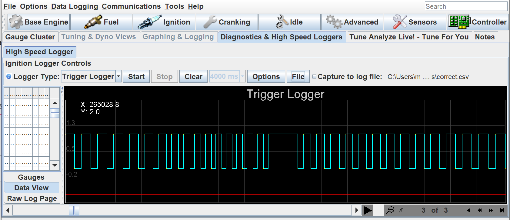
- Determine which of the below images matches your trigger pattern:
This is the correct missing tooth shape
This is the wrong missing tooth shape - swap your wires
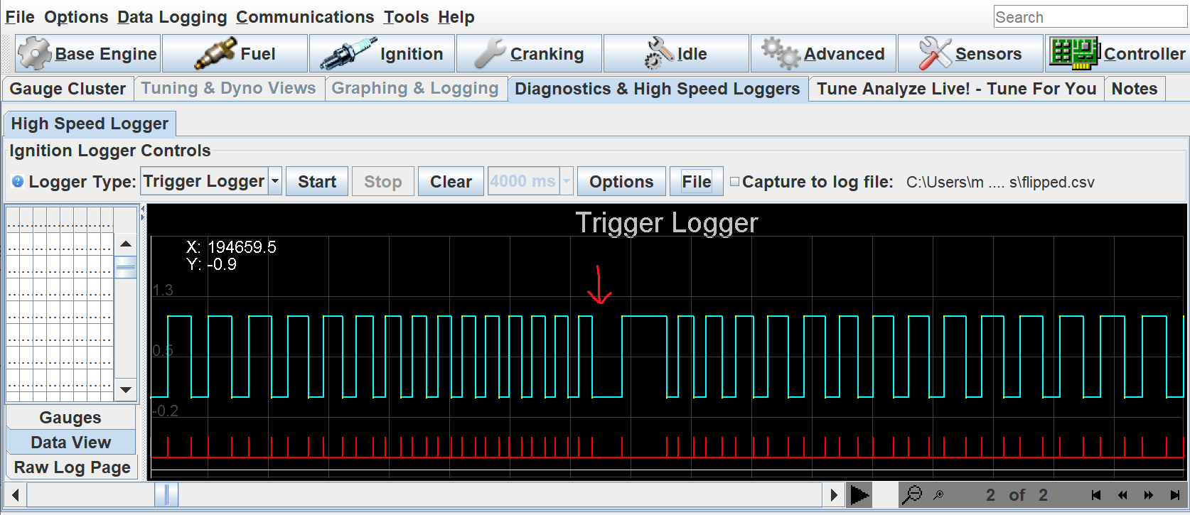
These images were collected on a Volvo 60-2 trigger wheel, the exact timing may vary, but a long period of low preceding the long high time (marked with arrow on the wrong image) is the clear indicator of a mis-wired sensor. The correct pattern is equally sized low periods, with a single long high period.
- If your missing tooth looks like the wrong example, swap the VR+ and VR- wires. Repeat steps 2-4, and double check that it now looks like the good example.
- In TunerStudio, ensure that "Use only rising edge" is set to
true, and "Invert Primary" is set tofalse. (found in the menu Base Engine > Trigger). These are the only correct combination of options for a MAX992x-based VR interface.
ECUs with "Bipolar" VR inputs (microRusEFI)
ECUs with bipolar VR sensor interfaces provide accurate zero-crossings for both directions, so inverting the polarity can be done in software, without hardware changes required. You will, however, need to look at the trigger log to determine whether or not to set the "Invert Primary" option.
Here is how to determine your trigger polarity with a bipolar input:
- Complete steps 1 thru 3 of the above procedure for unipolar inputs (crank the engine, collect a trigger log).
- Determine whether to set "Invert Primary":
- If your missing tooth is LOW, then HIGH (looks like the "wrong" example above), set "Invert Primary" to
true. - If your missing tooth is HIGH, then LOW (looks like the inverse of the "wrong" example), set "Invert Primary" to
false.
- If your missing tooth is LOW, then HIGH (looks like the "wrong" example above), set "Invert Primary" to
- In TunerStudio, ensure that "Use only rising edge" is set to
true.
I'm a Nerd and Want to Know More
Here are some oscilloscope screenshots of a different trigger wheel, in this case a 24-1 designed specifically for bench testing. It isn't particularly well matched to the sensor (hence the little squiggle on the zero crossing), but it works well enough to illustrate.
VR sensors output a voltage proportional to how quickly something conductive is moving toward/away from the sensor. This fact is exploited because when the sensor is centered on a tooth, the voltage will rapidly cross zero as the tooth approaches then departs. More good info and drawings here about how VR sensors work, and which edge you want to listen to
The green trace is the analog input to the MAX9924, and pink is the digital output (the same trace that's seen in the TunerStudio trigger log in the guides above).
First, here's the wrong polarity:
ToDo: add wrong polarity scope image
The output rising edge is well aligned to the falling edge zero crossing of the input, but that's the poorly-defined center of the missing tooth, not the sharp edges of the teeth.
And here's the correct polarity
ToDo: add correct polarity scope image
Now the "bad edge" of the missing tooth is a rising edge, and the good tooth centers are falling edges, which output a digital rising edge to the ECU.
See also How-Do-I-Set-My-Trigger-Offset