microRusEFI Kit Instructions
this page is outdated - rusEFI no longer sells microRusEFI as a kit
Initial kit state
All kit PCBs come pre-programmed and verified. No firmware upload required right after soldering. Actually your microRusEFI would communicate via USB if you solder just USB connector or feed USB via 48 pin connector.
VIDEO testing with test fixture
HOWTO microRusEFI Kit
microRusEFI kit used to come 75% assembled - while many components are already mounted, about two dozens still need to be added. This includes both easy to mount components like main connector and harder to solder TLE8888 100-pin chip. Some soldering hints and tricks are discussed here. If in doubt of your SMD skills please consider fully assembled version.
For component placement please use interactive BOM
All microRusEFI kits use MRE F4 rusEFI firmware - DOWNLOAD LATEST BUNDLE HERE
rusEFI Slack channel is the primary support channel.
HOWTO program rusEFI using DFU
Crankshaft position sensor options: Hall or VR
Depending on your crankshaft position sensor type you would need to populate either Hall or VR option.
0.4.5, 0.4.7: For VR crankshaft position sensor you would need to add R9 & C12 on the back.
0.4.8: Comes set for VR (R9 & C12 are now on the front since)
VR mode front - comes pre-assembled
VR mode back
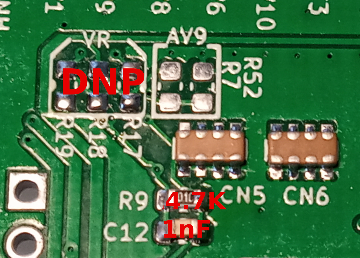
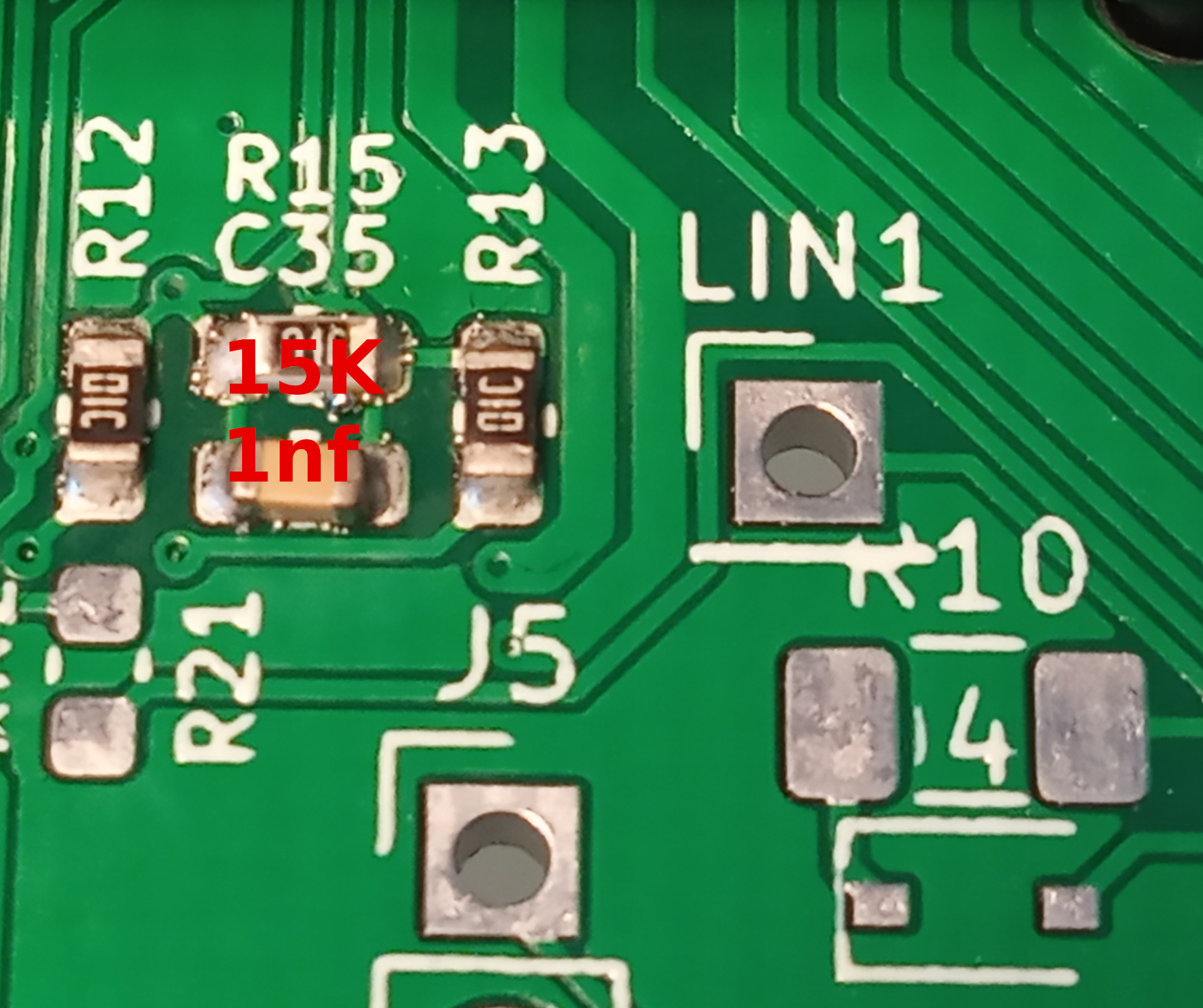
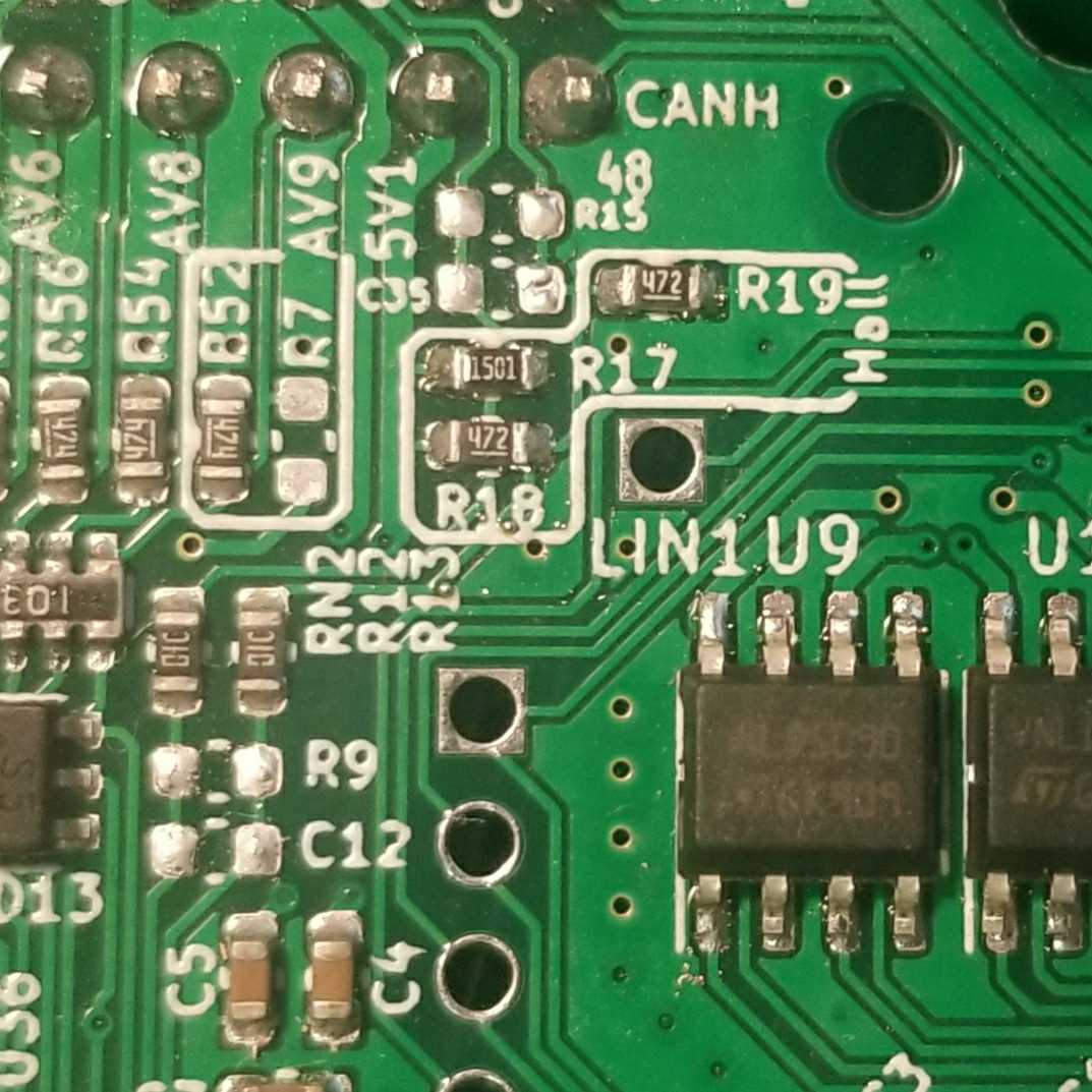
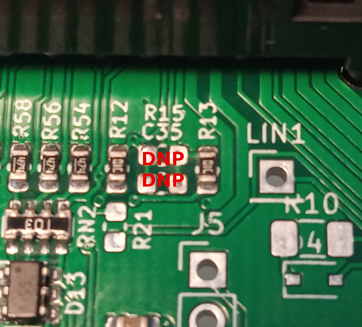
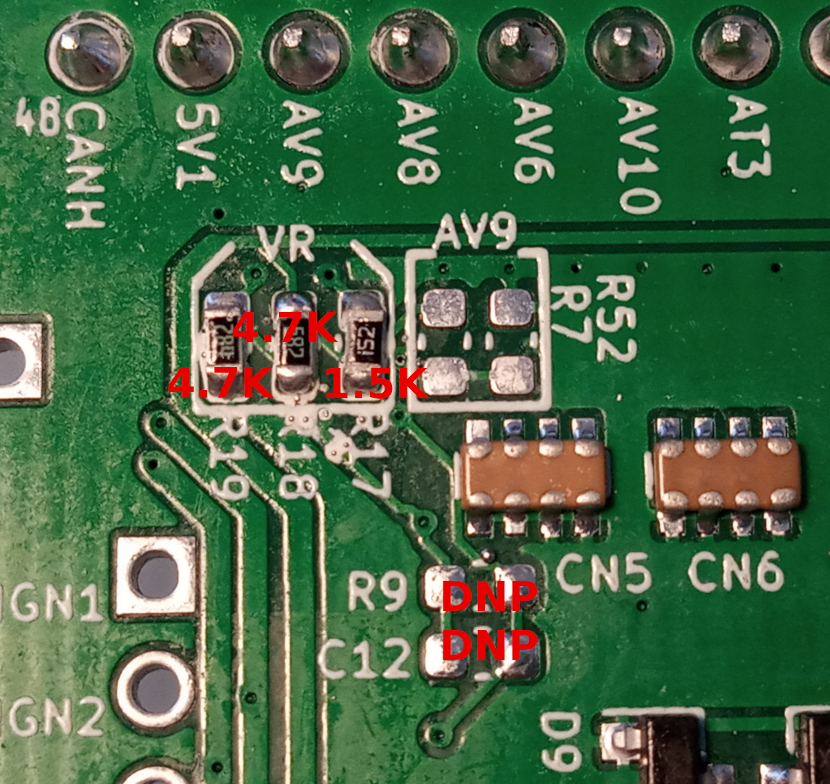
0.4.5, 0.4.7: For Hall, you would need to REMOVE R15 & C35 on the front, and install R17=1.5K R18=R19=4.7K on the back.
0.4.8: For Hall, you would need to REMOVE R15&R9, C12 & C35 on the front, and install R17=1.5K R18=R19=4.7K on the back.
0.5.0 Hall
0.4.7 Hall mode front
0.4.7 Hall mode back
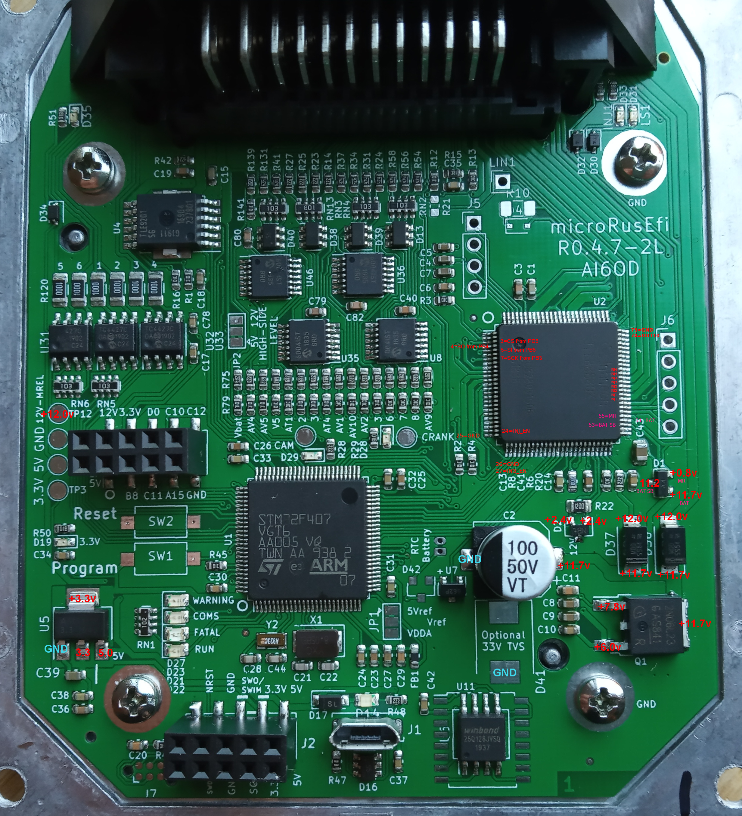
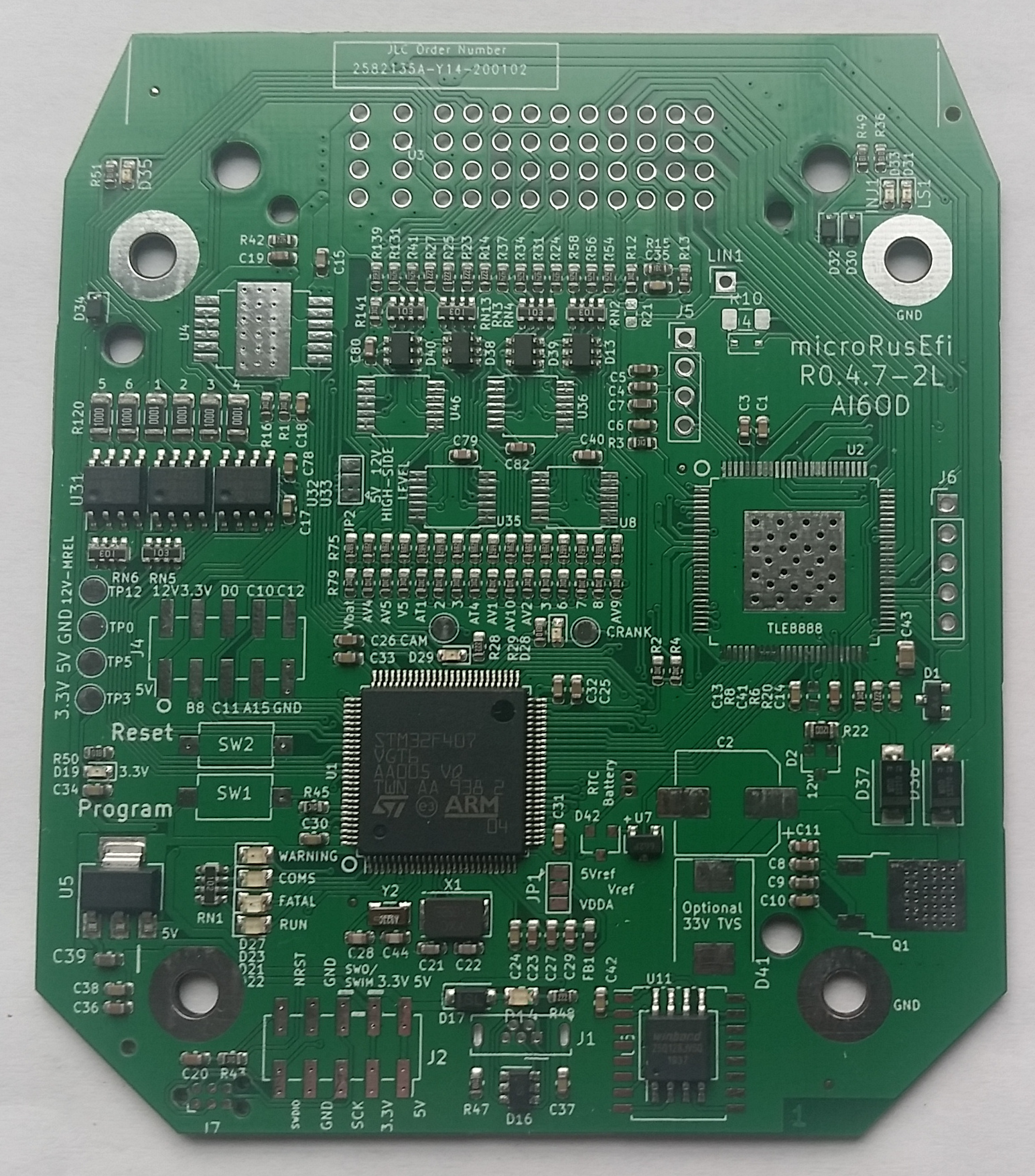
Board Photos
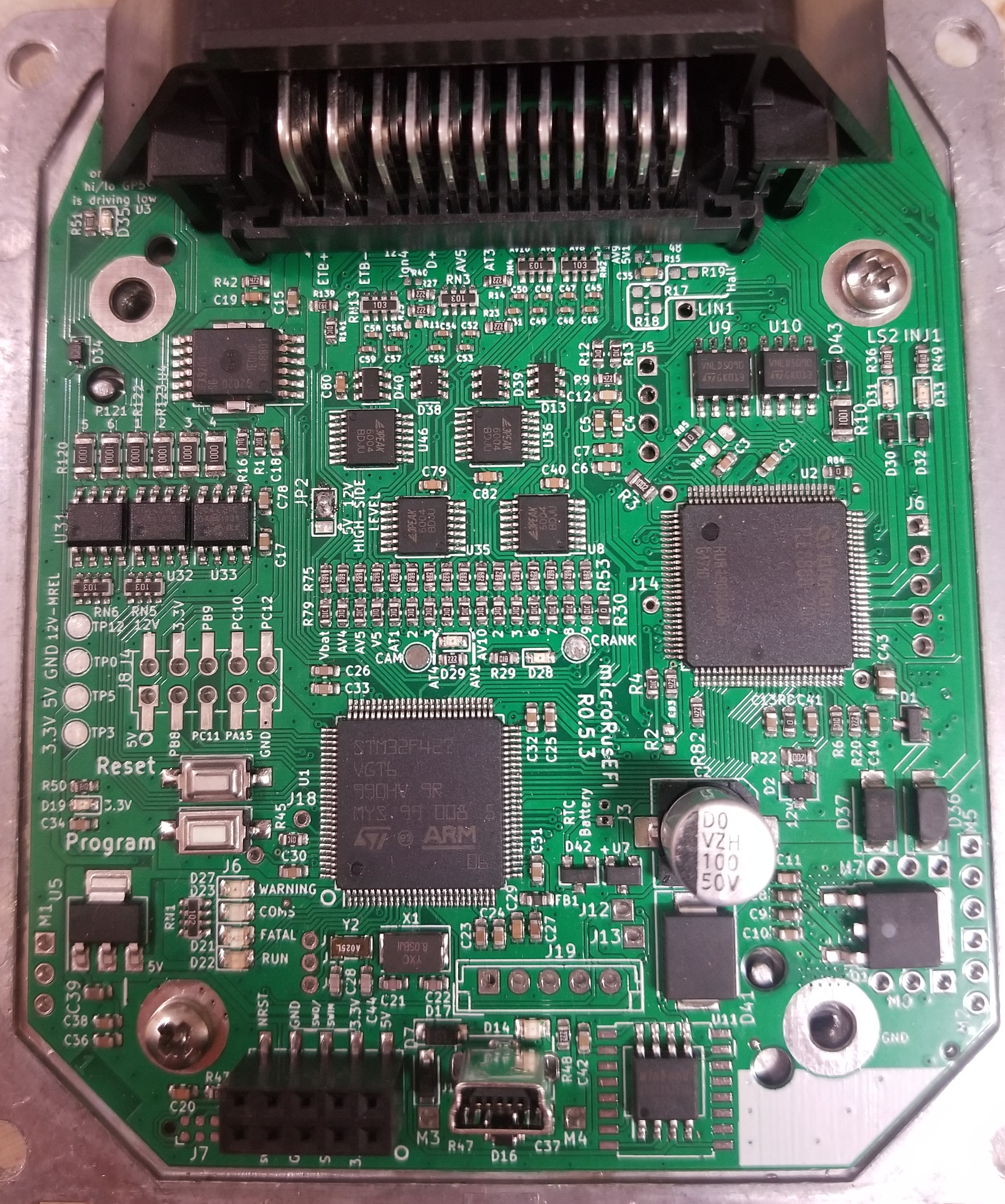
Kit front:
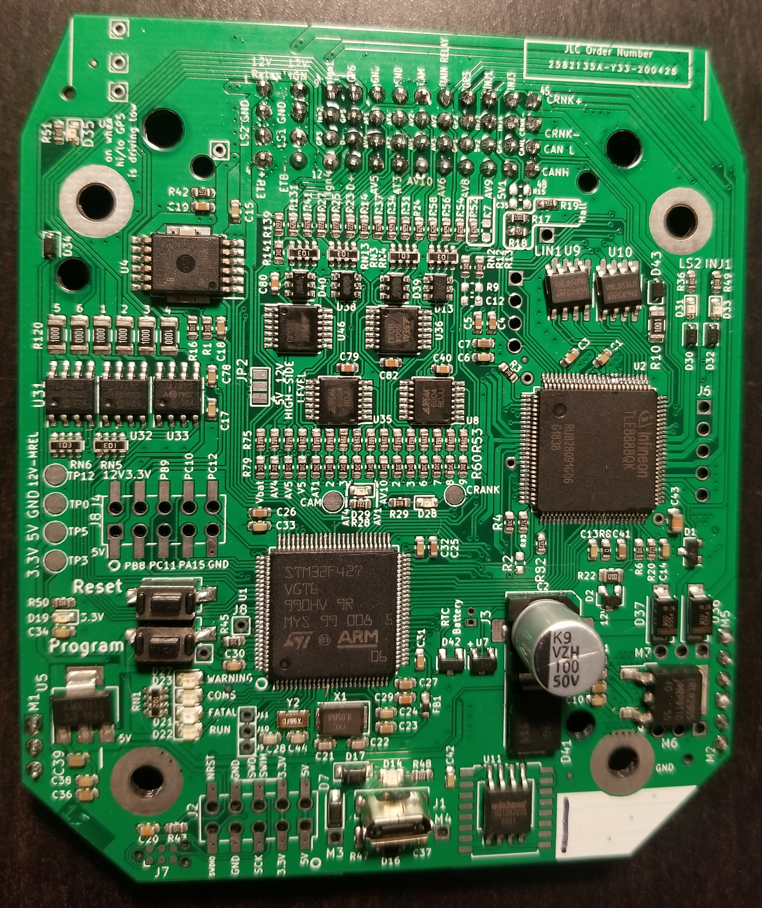
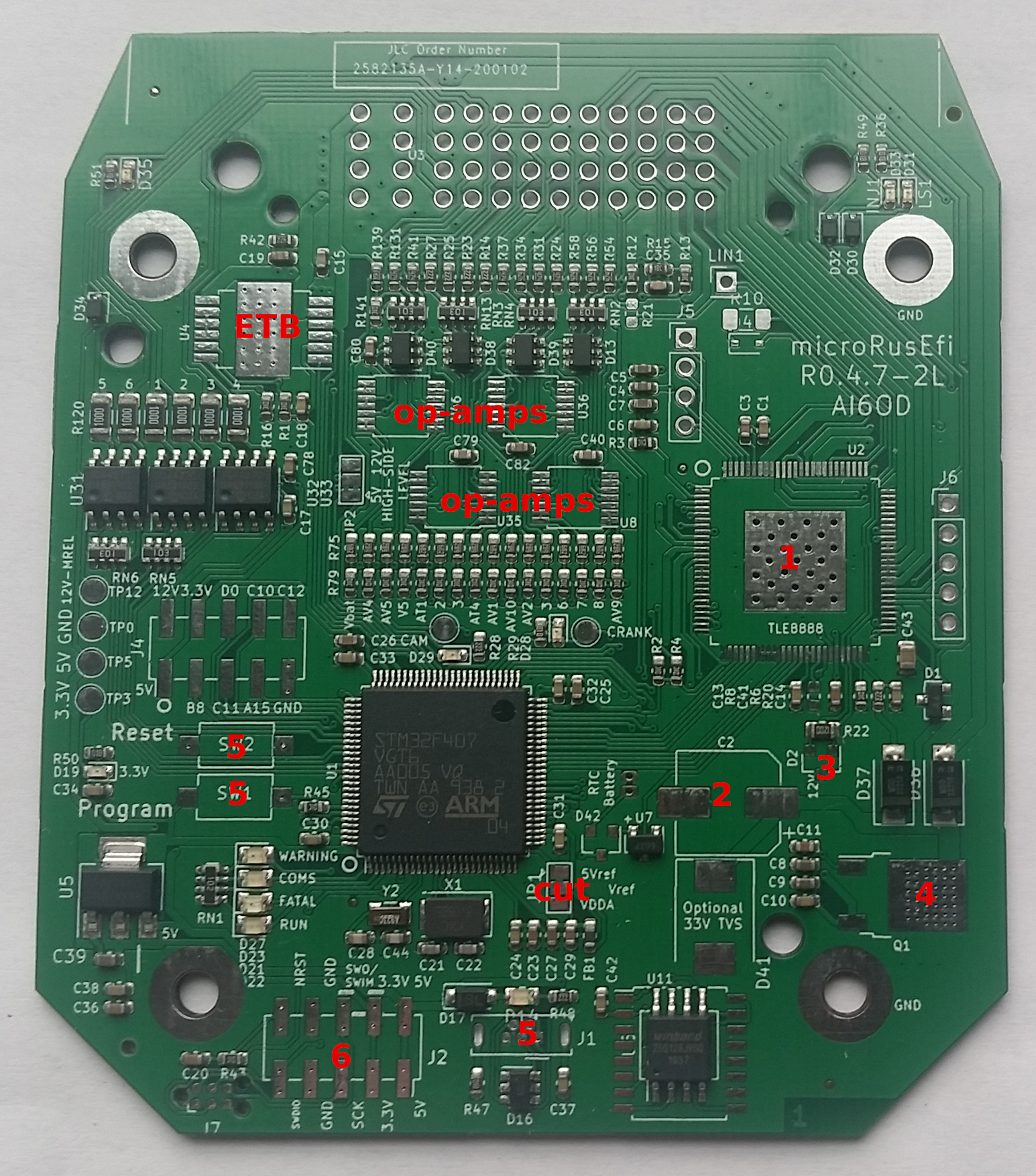
Kit parts on the front:
Kit parts on the back:
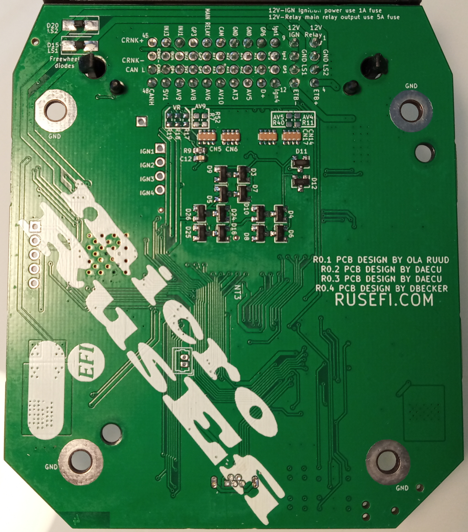
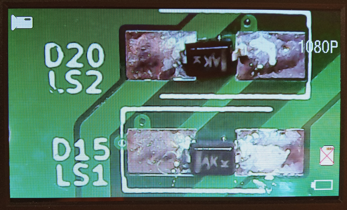
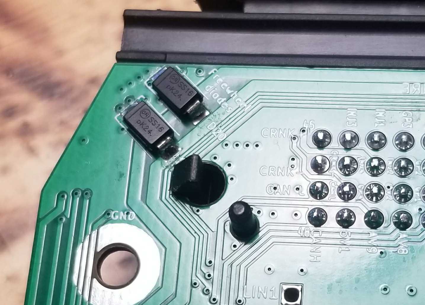
Diodes 0.4.7
Flyback diodes orientation around version 0.4.7 - horizontal facing OPPOSITE direction
Diodes 0.5.2
Flyback diodes orientation around version 0.5.2 - angles, facing SAME direction
Important details
0.4.5, 0.4.7: JP1 needs to be TBDsee
see https://github.com/rusefi/hw_microRusEfi/issues/127
Unpopulated parts which you probably do NOT need:
LIN termination D43 R10
RTC diode D42
Wake-up CAN R8
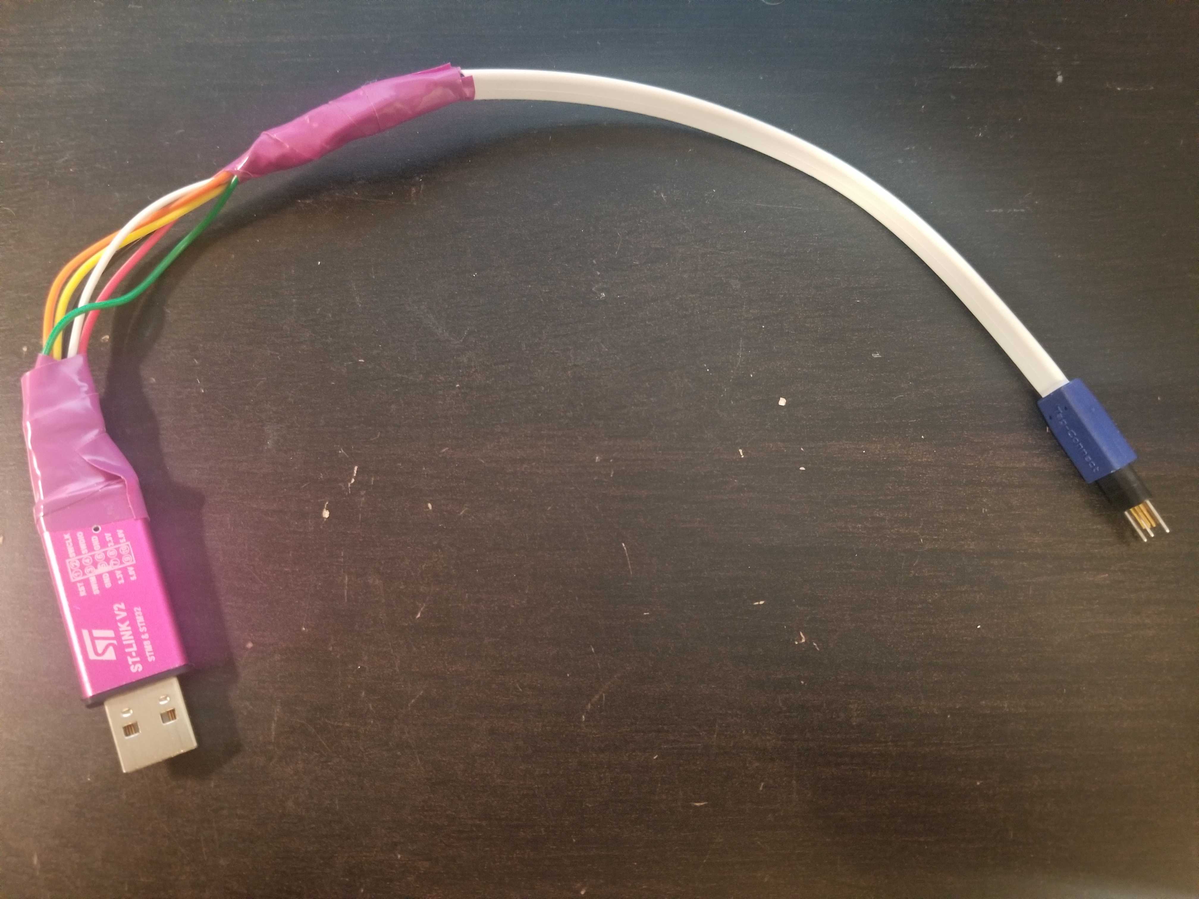
Direct board programming
J7 header in bottom-left corner of microRusEFI allows direct SWD programming using TC2030-MCP-NL cable
Tag Connect In circuit Cable "NO Legs" Version
Note - Missing wire caps
In the even of a missing wire cap on the molex plug the correct part number is 64320-1301 and these can be easily sourced online