Frankenstein
EFFECTIVELY RETIRED BOARD as of Dec 2021
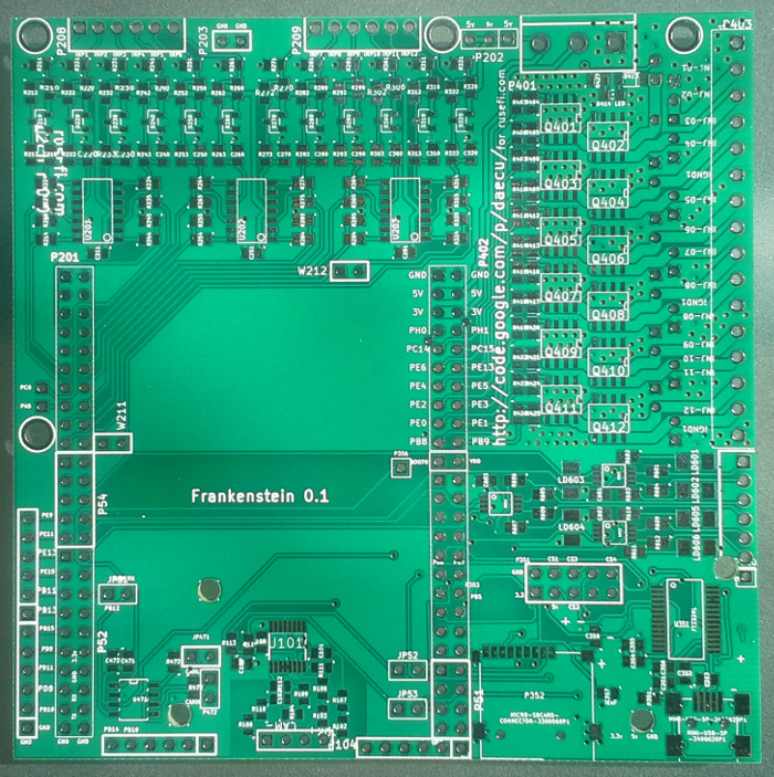
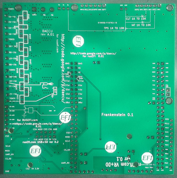
Bare PCB
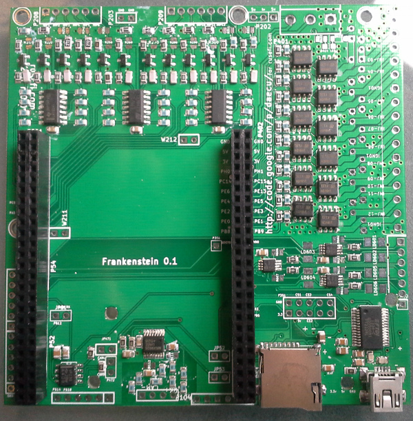
3D render
Assembly instructions
Step 1: MMC/SD card & USB TTL
Let's begin with communication module
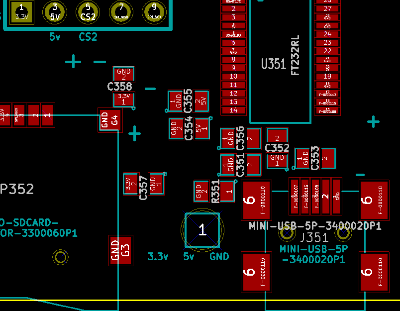
I'm impatient so P352 SD card module goes on first. Together with the right 25x2 header (P51/P353/P402) this gets me a working SD card. Hurray, this board is not a total failure! Now it's time to C357 to make things right.
Now USB TTL interface: it would not work if you just solder the U351 chip and the J351 miniUSB connector. C355 (0.1uF same thing as 100nF)
Step 2a: Hall sensor input
While we can use the MAX9926 VR chip for Hall sensor, the small chip is a hard to solder and the chip is relatively expensive - so I'd rather use op-amp channels for Hall sensor input. I have two Hall sensors so I would build two identical channels.
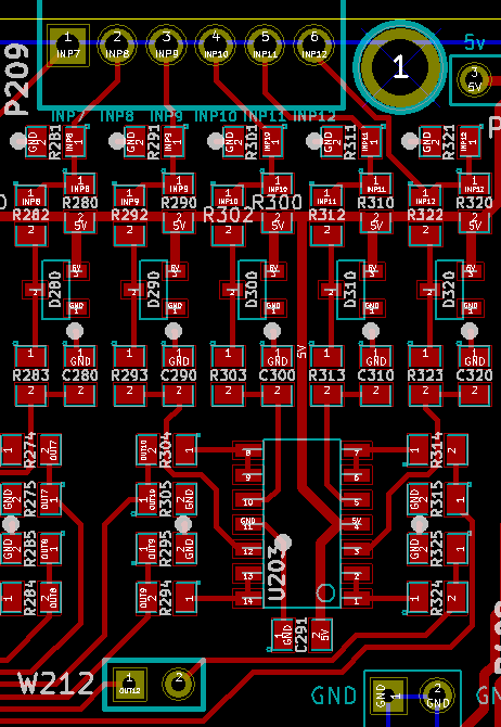
Both would use U203 quad op-amp C291 is 0.1uF C310 & C320: input RC filter 10000PF/0.01uF
Inp11 would be trigger channel1: R310 1K pull-up, R311 500K pull-down, R312 10K current limiting, R313 100 smth, R314 1.5K & R315 1.5K voltage divider. Inp12 would be trigger channel2: R320 1K pull-up, R321 500K pull-down, R322 10K current limiting, R323 100 smth, R324 1.5K & R325 1.5K voltage divider.
For trigger channel 1 there will be an ugly yellow wire between W211 and PC6, and for second channel it would be a green wire between W212 and PA5
step 3: Analog Inputs
The legend on the back assigns throttle position sensor to INP2 (stm pin PA3/ADC channel 3), intake air to INP3 (stm pin PC3/ADC 13) coolant temperature sensor to INP4 (stm pin PC1/ADC 11).
Inp2 (stm pin PA3/ADC3) would be throttle position sensor: no pull-up, R221 500K pull-down, R222 10K current limiting, R223 100 smth, R224 1.5K & R225 1.5K voltage divider. Inp3 (stm pin PC3/ADC13) would be intake air: R230 ??? pull-up, no pull-down, R232 10K current limiting, R233 100 smth, R234 1.5K & R235 1.5K voltage divider. Inp4 (stm pin PC1/ADC11) would be coolant temperature sensor: R24x ??? pull-up, no pull-down, R242 10K current limiting, R243 100 smth, R244 1.5K & R245 1.5K voltage divider.
Inp1 (stm pin PA1/ADC1) is my MAP sensor: no pull-up, R211 1K pull-down
Inp5 (stm pin PA0/ADC0) Battery voltage. Here we would need a voltage divider on the input side: R252 10K current limiting, R253 100 smth, R254 1.5K & R255 1.5K voltage divider.
High side driver
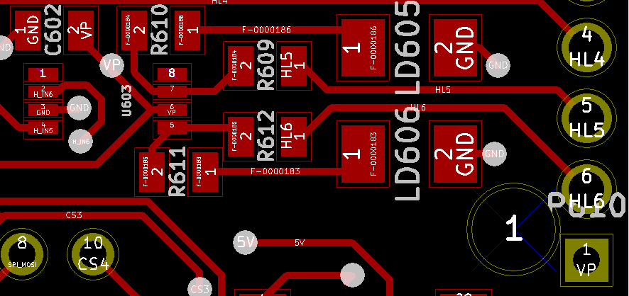
C601, C602 & C603 are 0.1uF R609, R612 - 100R
With the current issue - we've used MSOP case by mistake, this one is hard to solder. Be sure not to use too much paste. Not sure if you should even try it with soldering wire.
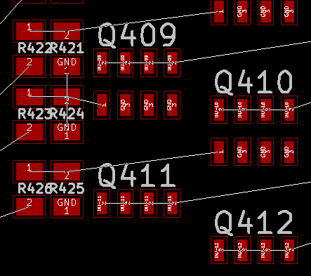
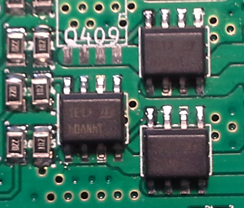
Low side driver
The resistors in the left row are 20R, the ones in the right row are 1K. The MOSFETs are mounted upside down: the notch should be on top, the part number & ST logo are upside down.
CAN module
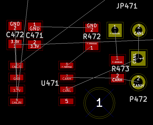
C471 is 0.1uF C472 is 4.7uF R472 10K something R473 120R CAN termination
VR input
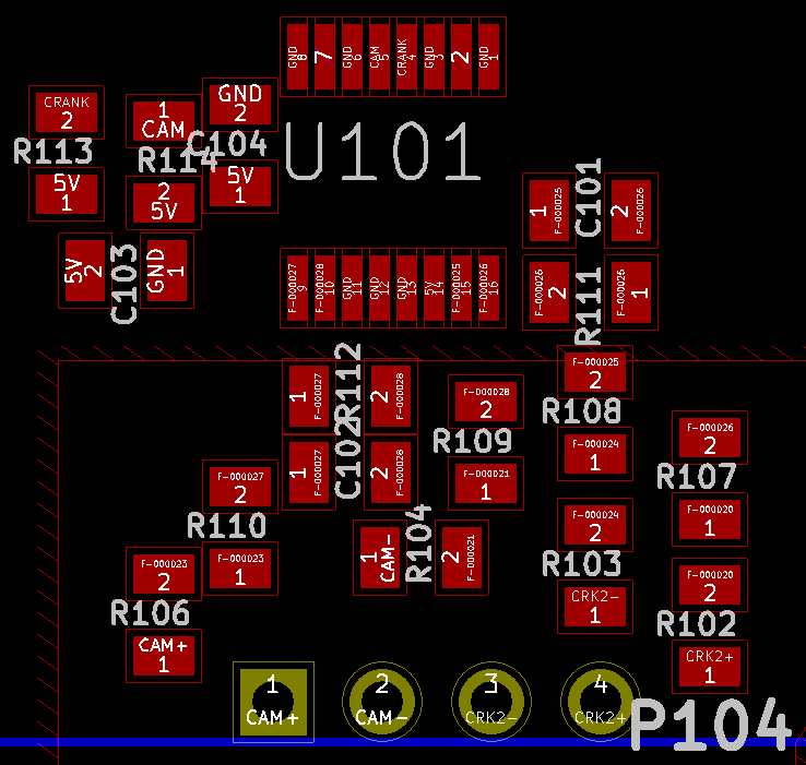
C101 & C102 are 1000pF C103 is 10uF C104 is 0.1uF R102, R103, R104, R106, R107, R108, R109 & R110 are 5K R113 & R114 are 10K
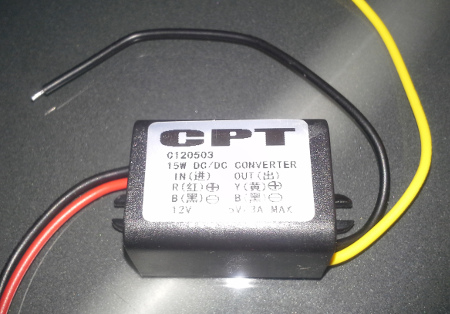
Random notes
We are still working on our own power supply, for now you would probably need a "12 to 5v power supply module" from eBay:
For the "low side to high side" hack you would need to mount through-hole resistors in a tower/Manhattan style.
There is no SD module part number from a major US supplier. TODO: figure this out, but just get them on eBay - see forum thread
FT232 validation:
pin 15: USBDP 1.5K pull-up to to 3.3 - green USB wire pin 16: USBDM - white USB wire pin 17: 3vout
Q: 'USB Device cannot be recognized'?
A: Take a spare USB cable & cut it to check continuity between white wire and pin 16.