How to M73 V12 on Proteus
- 💲rusEFI Proteus💲 can run a M70/M73 port-injected v12.
- We do not support unusual M73 throttle bodies; we also only support 6 wire pedal position sensors. Nissan throttle bodies are the best fit we have found for M73
- MAP sensor fuel control strategy is recommended; that would require MAP sensor to be fitted on the engine
See also HOWTO-Crimp-Ampseal.
See also Vault-Of-Electronic-Throttle-Bodies-ETB.
The Nissan Hitachi SERA576-01 60mm throttle body is recommended. In order to mount the SERA576-01 you just need to drill ETB bolt passages to 10mm / 3/8".
About six wires are different between Proteus 0.2 and Proteus 0.3+ - all on the 23-pin plug.
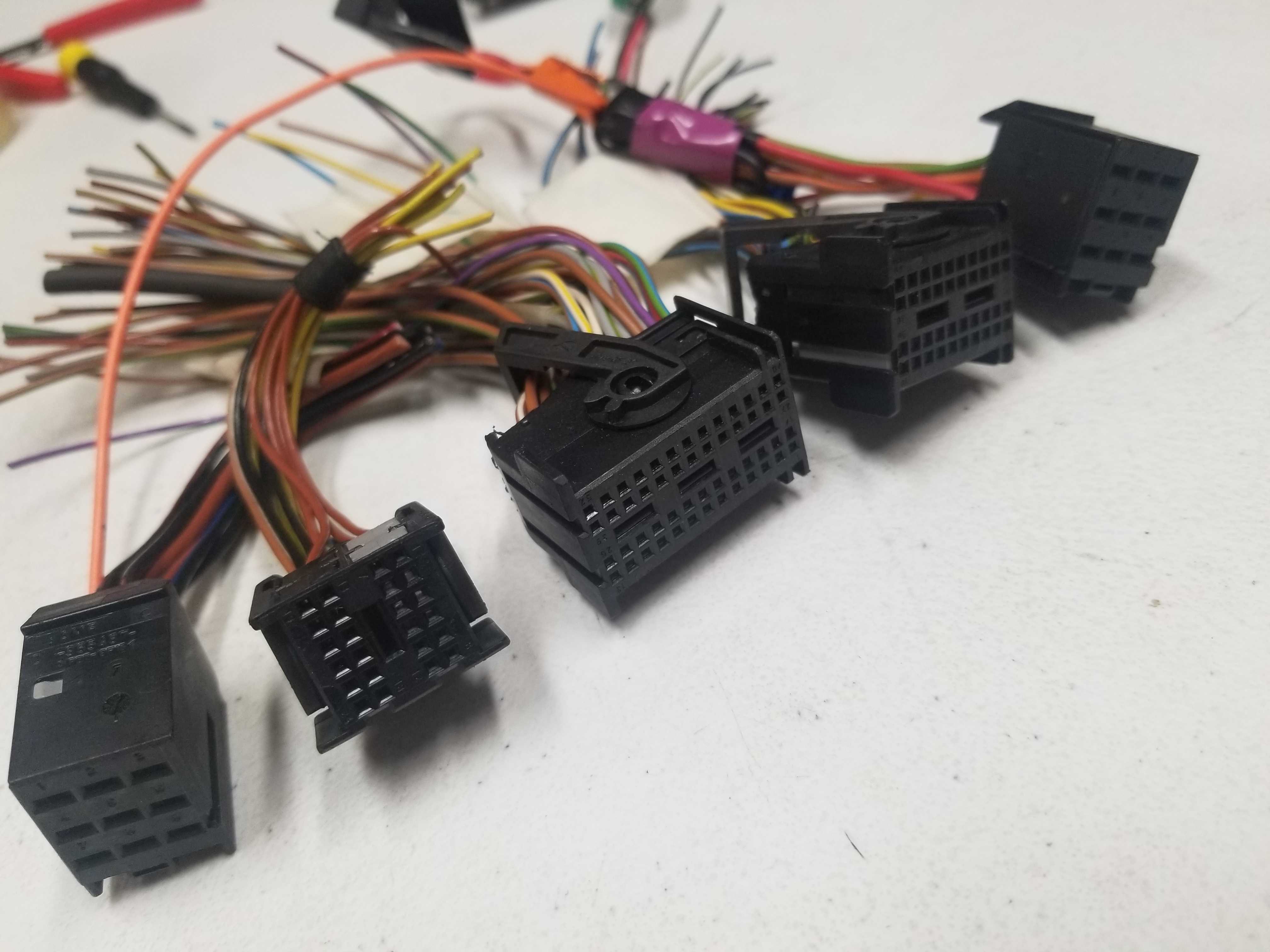
This HOWTO focuses on M73 engine with a stock ECU harness. The 1998 stock ECU harness has two 134-pin connectors.
The 1998 example used as a test mule has a black connector and a grey connector. Each connector has 9+24+52+40+9=134 pins total.
rusEFI uses six wire colors: black white red orange green blue.
Proteus
- +12V from main relay
- 12 injectors
- CLT
- IAT
Total wires between Proteus and the grey connector: 10 Total wires between Proteus and the black connector: 22
Destination legend: "Black #3 40/52" means "Black set of ECU plugs, connector #3 - pin 40 of 52 total pins"
Black 35 Pin 776231-1
| Pin Number | Name | Type ID | Default function | rusEFI color | new color | Destination |
|---|---|---|---|---|---|---|
| 3 | Lowside #1 | ls | Injector #1 | Blue | PURPLE | Black #3 41/52 BRN/WHT |
| 4 | Lowside #3 | ls | Injector #3 | Green | YELLOW | Black #3 40/52 |
| 5 | Lowside #5 | ls | Injector #5 | Red | PINK | Black #3 28/52 |
| 6 | Lowside #6 | ls | Injector #6 | Orange | ORANGE | Black #3 27/52 BRN/BLK |
| 7 | Lowside #7 | ls | Injector #7 | Blue | PURPLE | Grey #3 41/52 BRN/WHT |
| 8 | Lowside #9 | ls | Injector #9 | Green | YELLOW | Grey #3 40/52 |
| 9 | Lowside #11 | ls | Injector #11 | Red | PINK | Grey #3 28/52 |
| 10 | Lowside #13 | ls | low-side output: main relay | Blue | PURPLE | Black #2 23/24 BRN/BLK |
| 11 | Lowside #14 | ls | low-side output: starter enable | White | WHITE | Black p #4 40/40 YEL/BRN |
| 12 | Lowside #15 | ls | low-side output: radiator fan relay | green | YELLOW | accessory |
| 15 | Lowside #2 | ls | Injector #2 | Black | BROWN | Black #3 15/52 |
| 16 | Lowside #4 | ls | Injector #4 | White | WHITE | Black #3 2/52 |
| 17 | GND | y | Power GND | Black | BROWN | Grey #1 4/9 |
| 18 | GND | y | Power GND | Black | BROWN | Black #1 4/9 |
| 19 | Lowside #8 | y | Injector #8 | Black | BROWN | Grey #3 15/52 |
| 20 | Lowside #10 | y | Injector #10 | White | WHITE | Grey #3 2/52 |
| 21 | Lowside #12 | y | Injector #12 | Orange | ORANGE | Grey #3 27/52 BRN/BLK |
| 23 | Lowside #16 | y | low-side output: fuel pump | Orange | ORANGE | accessory |
| 24 | GND | y | Power GND | Black | BROWN | Grey #1 6/9 BRN |
| 30 | Ignition 7 | y | Ignition cylinder 7 | White | WHITE | External Igniter channel #2 |
| 35 | Ignition 1 | y | Ignition cylinder 1 | Orange | ORANGE | External Igniter channel #1 |
Unused pins are - 1;2;13;14;25;26;27;28;29;31;32;33;34;
Black 23 Pin 776228-1 on Black Proteus 0.2
| Pin Number | Name | Type ID | Default function | rusEFI color | OEM connector |
|---|---|---|---|---|---|
| 1 | DIGITAL 2 | din | Camshaft position sensor | Red | Black #3 20/52 |
| 2 | DIGITAL 3 | din | Start button | Orange | accessory |
| 5 | VR1 pos | vr | Variable Reluctance #1 positive | Orange | Black #3 32/52 |
| 8 | ETB1- | y | ETB 1 negative | White | |
| 13 | VR1 neg | vr | Variable Reluctance #1 negative | Blue | Black #3 46 /52 |
| 15 | ETB1+ | etb | ETB 1 positive | Blue | |
| 18 | +12 raw | 12v | ignition power / ECU power source | Red | Black #4 26/40 GRN/BLK |
| 19 | GND | y | Power GND | Black | Black #1 6/9 BRN |
| 21 | ETB2- | etb | ETB 2 negative | White | |
| 22 | ETB2+ | etb | ETB 2 positive | Blue | |
| 23 | +12V mr | 12v | ETB/high-side power supply from main relay | Red | Black #1 8/9 RED/BLU |
End of Black Proteus 0.2 23 pin table
Black 23 Pin 776228-1 on Green Proteus 0.3+
| Pin Number | Name | Type ID | Default function | rusEFI color | new color | OEM connector |
|---|---|---|---|---|---|---|
| 1 | DIGITAL 2 | din | Camshaft position sensor | Red | PINK | Black #3 20/52 |
| 2 | DIGITAL 3 | din | Start signal from ignition key | Orange | ORANGE | |
| 5 | VR1 pos | vr | Variable Reluctance #1 positive | Orange | ORANGE | Black #3 32/52 |
| 6 | ETB1- | y | ETB 1 negative | White | WHITE | |
| 7 | ETB1+ | etb | ETB 1 positive | Blue | PURPLE | |
| 8 | ETB2- | etb | ETB 2 negative | White | WHITE | |
| 13 | VR1 neg | vr | Variable Reluctance #1 negative | Blue | PURPLE | Black #3 46 /52 |
| 15 | ETB2+ | etb | ETB 2 positive | Blue | PURPLE | |
| 16 | CAN- | can | CAN bus low | White | WHITE | accessory |
| 17 | CAN+ | can | CAN bus high | Red | PINK | accessory |
| 18 | +12 raw | 12v | ignition power / ECU power source | Red | PINK | Black #4 26/40 GRN/BLK |
| 19 | GND | y | Power GND | Black | BROWN | Black #1 6/9 BRN |
| 23 | +12V mr | 12v | ETB/high-side power supply from main relay | Red | PINK | Black #1 8/9 RED/BLU |
End of Green Proteus 0.3+ 23 pin table
Unused pins are - 3;4;;9;10;11;12;14;20;21;22;
White 35 Pin 776231-2
| Pin Number | Name | Type ID | Default function | rusEFI color | new color | OEM connector |
|---|---|---|---|---|---|---|
| 1 | GND | sgnd | Sensor GND | Black | BROWN | Black #3 21/52 BRN |
| 2 | GND | sgnd | Sensor GND | Black | BROWN | ETB #1 sensor GND |
| 3 | GND | sgnd | Sensor GND | Black | BROWN | ETB #2 sensor GND |
| 4 | GND | sgnd | Sensor GND | Black | BROWN | Grey #3 47/52 BRN |
| 5 | GND | sgnd | Sensor GND | Black | BROWN | Throttle Pedal Position GND #1 |
| 6 | GND | sgnd | Sensor GND | Blue | PURPLE | Throttle Pedal Position GND #2 |
| 7 | GND | sgnd | Sensor GND | Black | BROWN | Accessory / MAP gnd |
| 8 | GND | sgnd | Sensor GND | BROWN | Black #3 50/52 Knock Shield/GND | |
| 9 | 5V SENS 1 | 5v | Analog Voltage +5 supply #1 | Red | PINK | ETB #1 sensor +5v feed |
| 10 | 5V SENS 2 | 5v | Analog Voltage +5 supply #2 | Red | PINK | Throttle Pedal Position +5v feed #1 |
| 14 | AV3 | av | Analog Voltage Input #3 | Orange | ORANGE | TPS1 Secondary signal |
| 15 | AV5 | av | Analog Voltage Input #5 | Orange | ORANGE | TPS2 Secondary signal |
| 16 | AV7 | av | Analog Voltage Input #7 | White | White | Throttle Pedal Position #2 signal |
| 21 | 5V SENS 1 | 5v | Analog Voltage +5 supply #1 | Orange | ORANGE | Throttle Pedal Position +5v #2 |
| 22 | 5V SENS 2 | 5v | Analog Voltage +5 supply #2 | Red | PINK | Accessory / MAP +5V feed |
| 23 | GND | sgnd | Sensor GND | ORANGE | Grey #3 37/52 Knock Shield/GND | |
| 24 | AV2 | av | Analog Voltage Input #2 | Green | YELLOW | TPS1 Primary signal |
| 25 | AV4 | av | Analog Voltage Input #4 | Green | YELLOW | TPS2 Primary signal |
| 26 | AV6 | av | Analog Voltage Input #6 | Green | YELLOW | Throttle Pedal Position #1 signal |
| 27 | AV8 | av | Analog Voltage Input #8 | Blue | PURPLE | MAP/MAF accessory |
| 28 | AV10 | av | Analog Voltage Input #10 | Green | YELLOW | AFR/WBO accessory |
| 30 | AT2 | at | Intake air temperature IAT | Orange | ORANGE | Grey #3 34/52 |
| 31 | AT4 | at | Coolant temperature CLT | Green | YELLOW | Black #3 22/52 RED/BRN |
| 32 | 5V SENS 1 | 5v | Analog Voltage +5 supply #1 | Red | PINK | ETB #2 sensor +5v feed |
| 34 | knock | Knock #1 | ORANGE | Black #3 49/52 | ||
| 35 | knock | Knock #2 | PURPLE | Grey #3 36/52 |
Unused pins are - 8;11;12;13;17;18;19;20;23;29;34;35;
Wire length:
ETB/Pedal: 7ft/213cm
ECU/OEM pigtails: 52 inches / 132cm
| Color | Quantity on 35 Black |
|---|---|
| Orange | 4 |
| Red | 2 |
| White | 4 |
| Blue | 3 |
| Black | 5 |
| Green | 3 |
| Total | 21 |
| Color | Quantity on 23 Black |
|---|---|
| Orange | 2 |
| Red | 4 |
| White | 3 |
| Blue | 3 |
| Black | 1 |
| Green | 0 |
| Total | 13 |
| Color | Quantity on 35 white |
|---|---|
| Orange | 4 |
| Red | 4 |
| White | 1 |
| Blue | 2 |
| Black | 6 |
| Green | 5 |
| Total | 22 |
| Color | Total Proteus Quantity | Short | Long |
|---|---|---|---|
| Orange | 10 | 7 | 3 |
| Red | 10 | 7 | 3 |
| White | 8 | 5 | 3 |
| Blue | 8 | 5 | 3 |
| Black | 12 | 9 | 3 |
| Green | 8 | 5 | 3 |
| Total | 56 | 38 | 18 |
| Color | Accessory function |
|---|---|
| Orange | Start button |
| White | CAN |
| Red | CAN |
| Red | MAP 5v |
| Black | MAP GND |
| Blue | MAP Signal |
| Green | AFR WBO Signal |
| Green | Radiator Fan Relay |
| Orange | Fuel Pump Relay |
9 pin plug #1
| Pin Number | Name | Type ID | Default function | rusEFI color | OEM connector |
|---|---|---|---|---|---|
| . | |||||
24 pin plug #2
| Pin | type | OEM color | Description | rusEFI color |
|---|---|---|---|---|
52 pin plug #3
| Pin | type | OEM color | Description | rusEFI color |
|---|---|---|---|---|
40 pin plug #4
| Pin | type | OEM color | Description | rusEFI color |
|---|---|---|---|---|
| 6 | IN | start signal from ignition key | ||
| 17 | OUT | BLK | engine speed output for gauge cluster | |
| 26 | IN | GRN/BLK | RED +12v hot in start & run | |
| 40 | OUT | YEL/BRN | BRN starter enable | |
9 pin plug #5
| Pin | type | OEM color | Description | rusEFI color |
|---|---|---|---|---|
| 3 | OUT BLK | ORANGE | coil signal, low-side | |
| 5 | GND BRN | GND | ground | |
| 6 | OUT BLK | ORANGE | coil signal, low-side | |
| 9 | OUT BLK | ORANGE | coil signal, low-side | |
Toyota coil output pin #10 GREEN goes to BLACK breakout
Toyota coil output pin #1 YELLOW goes to GREY breakout
Toyota GND pin #3 goes to both BLACK and GREY breakout #5 5/9
Toyota Battery pin #9 to both BLACK and GREY breakout #1 8/9
- Plug #5 9 pin
- ECU pin 3: OUT BLK RED coil signal, low-side
- ECU pin 5: GND BRN GND ground
- ECU pin 6: OUT BLK RED coil signal, low-side
- ECU pin 9: OUT BLK RED coil signal, low-side
See also the Vault of Electronic Throtttle Bodies
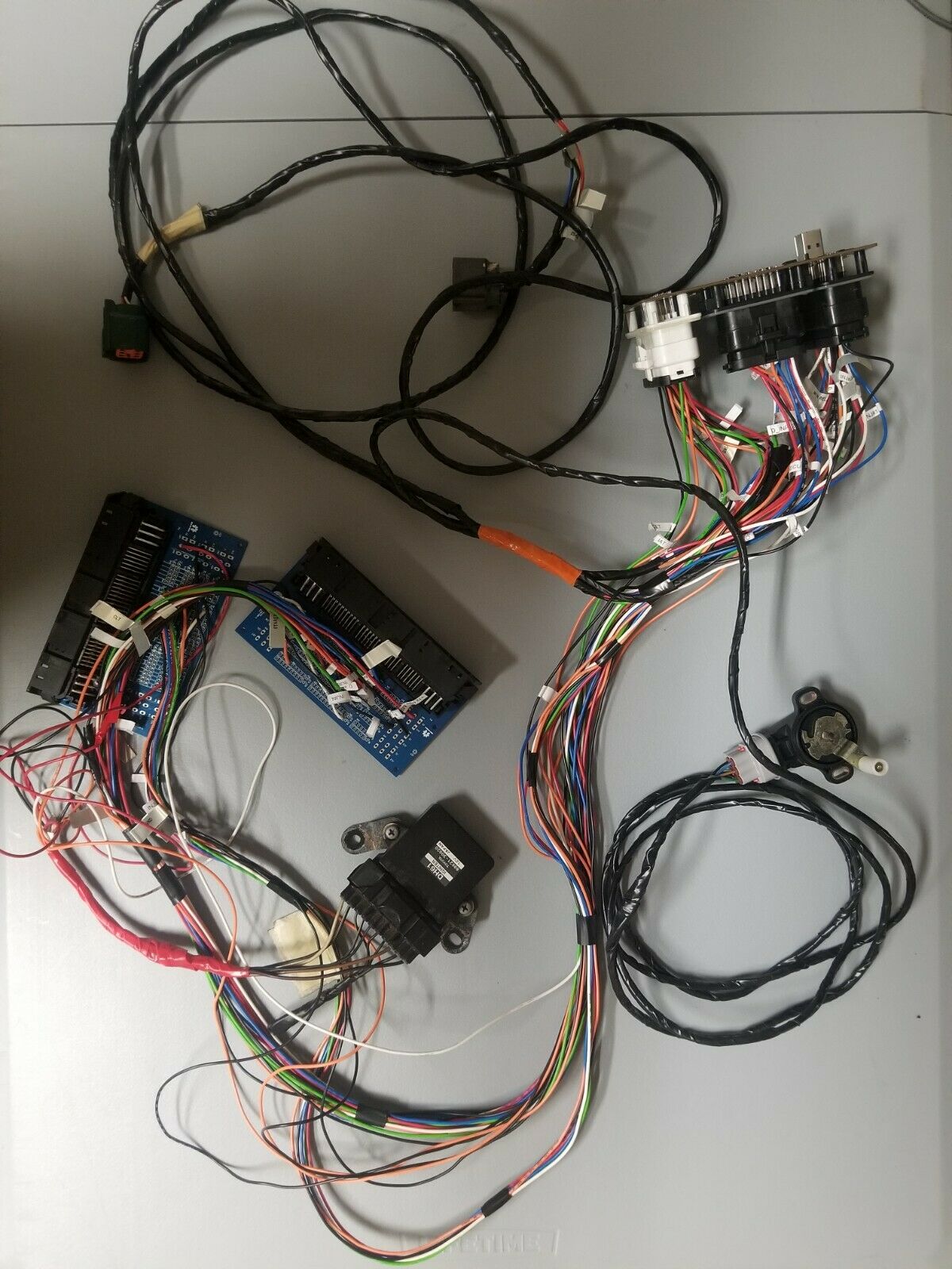
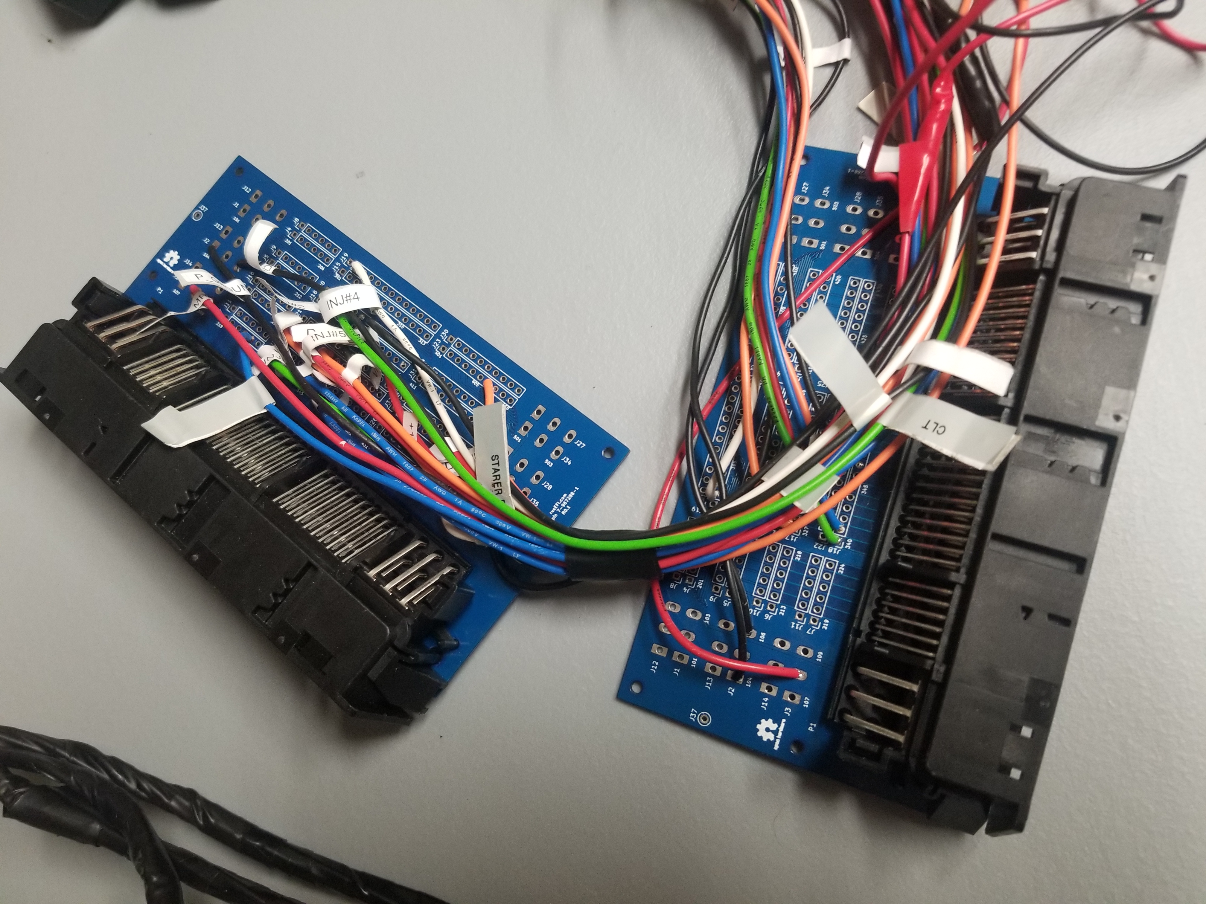
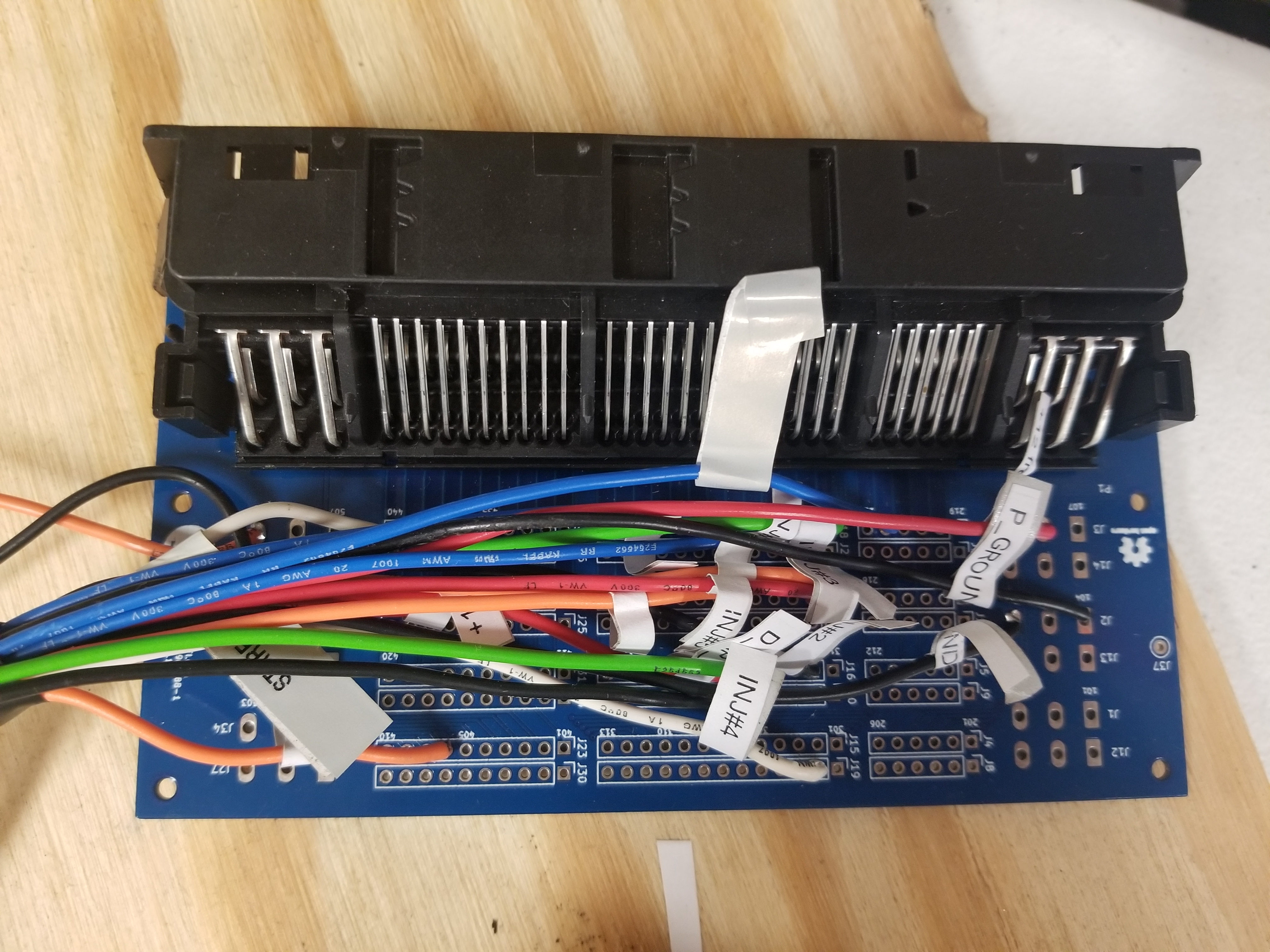
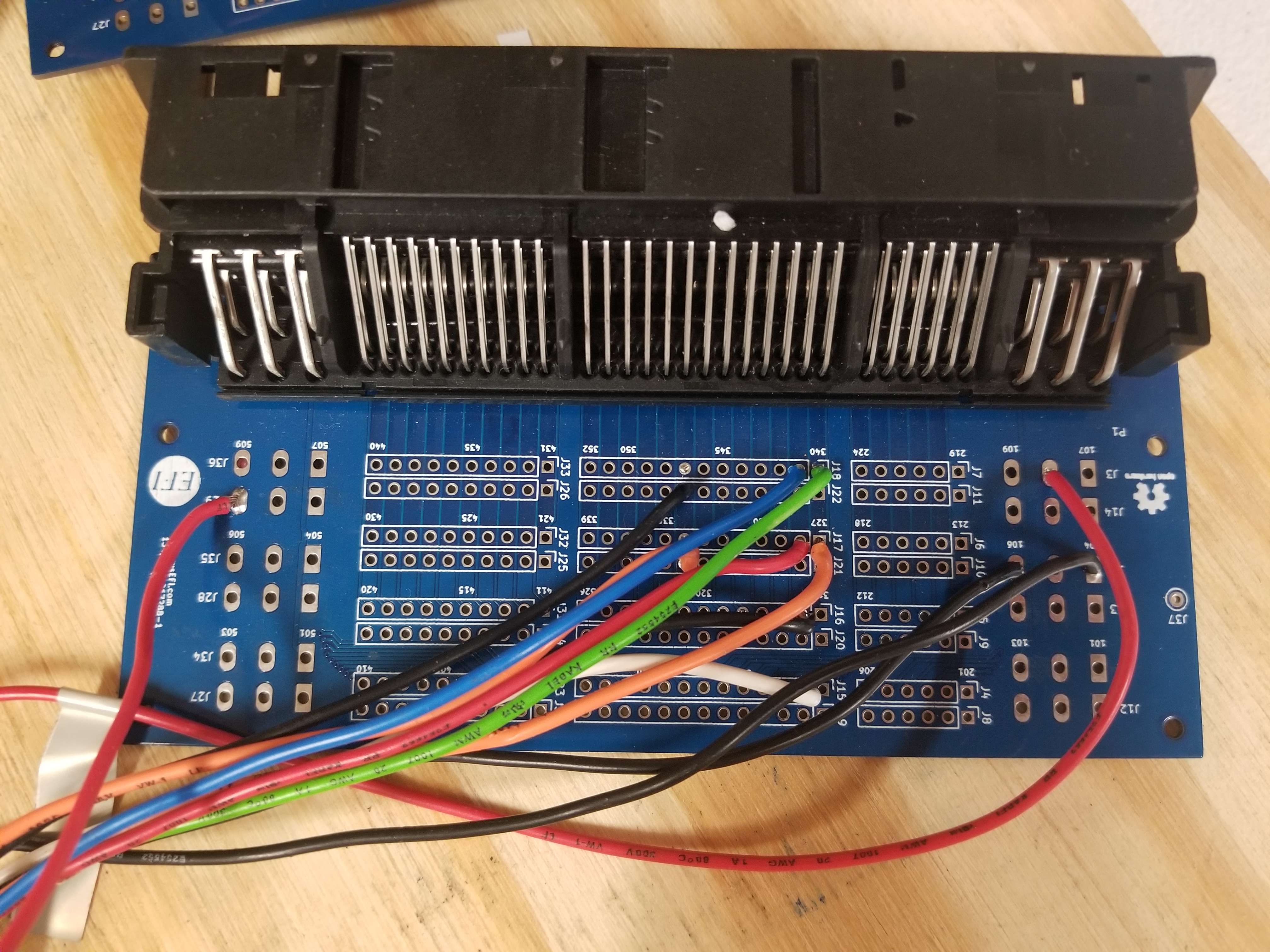
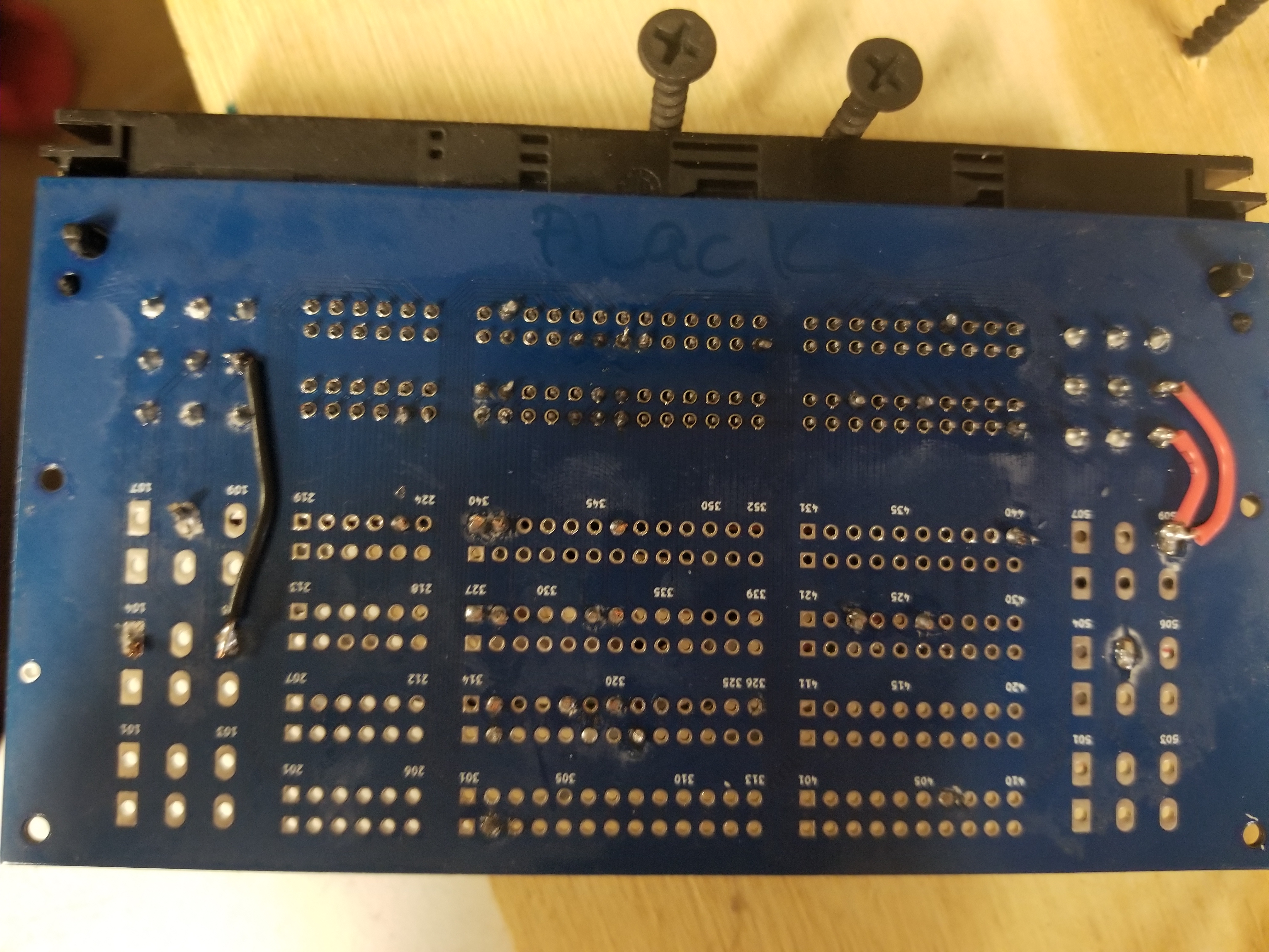
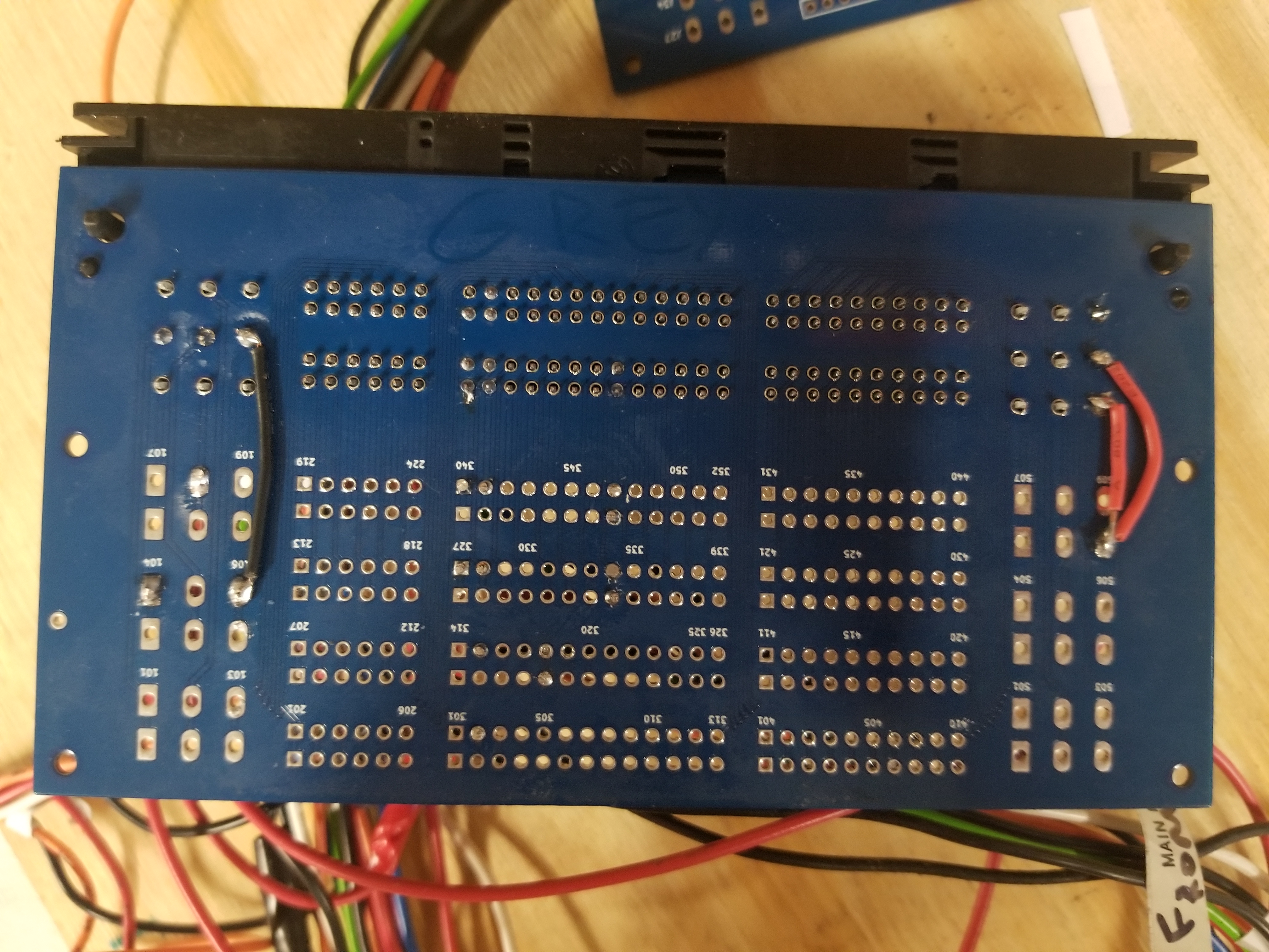
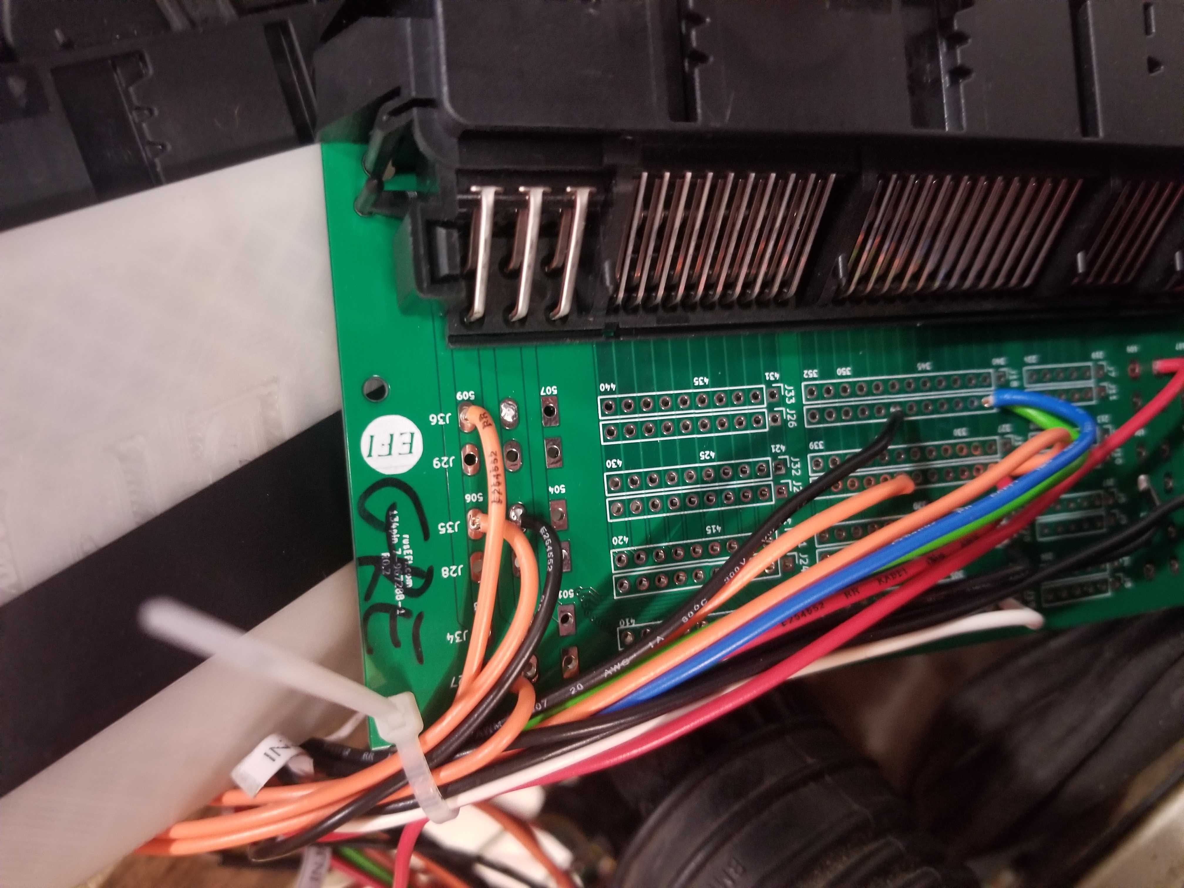
Pictured is a Proteus with ampseal connectors, non-BMW pedal sensor, two non-BMW ETB connectors, ignitor, and two breakout boards for the stock connectors.
The OEM pedal and ETBs are too unusual, thus a complete redesign of pedal and ETB hardware and wiring was expedient.