HOWTO M111 on microRusEFI
See also Mercedes-OEM-ECU
See also Custom-M111-Full-Engine-Harness
See also OEM-harness-connectors#mercedes
- Important suggestion: use a Honda accelerator pedal position sensor (PPS) in the engine bay not a Mercedes pedal position sensor
- Honda OE part numbers: 37971-RBB-003, 37971-PZX-003, 37971-RCA-A01, 37971-RDA-A01
- Replace Part Numbers: 5S8776, APS147, PPS1046, 72-7080, 1802-300281, 2-80046, SU10238, 699-199, 699199.
-
Connector: 6-way Pigtail for Honda Acura Throttle pedal sensor
-
Less important trick: 4-wire GM MAP+IAT
-
Less important trick: fuel pressure mod
Making my 190e More Fun (M111 SC Swap) - Forum
OEM C230 and SLK230 Wiring Diagrams
W202 C180 M111.921 with ME2.1
Getting started with the W202 ME2.1 ECU connector
This ECU has a CAR connector with 145 pins. Diagram with diagnostic pin assignment can be found here
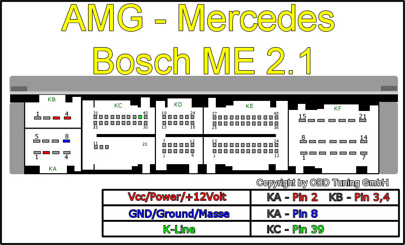
How to read the following table:
Connector: Connector from A to F on the harness.
Pin: Pin number of the connector.
Name: this field was filled from the M111.921 wiring diagram.
Function: some human readable text.
ME2.1 Description: Based on me2.1 documenation what I have found for Alfa Rome.
MRE pin: Where to connect the pin (wiring example).
Comments: extra info that I learned during wiring in the ECU.
| Connector | Pin Number | Name | Function | ME2.1 Description | MRE pin | Comments |
|---|---|---|---|---|---|---|
| A | 1 | NC | NC | NC | NC | |
| A | 2 | 12V ACC | Supply | Supply | MRE pin 1,5 | 12v Supply when ignition is on. |
| A | 3 | KL31(GND) | Ground | Ignition earth | MRE pin 2,6 | Supply earth |
| A | 4 | NC | NC | NC | NC | |
| A | 5 | O2 LSS | O2 Heater | Lambda sensor heater | NC | Only if you plan to use factory NB O2 sensor |
| A | 6 | FAN Control | PWM to Fan control module | Relay for 1st Fan Control | MRE pin 33 (GP3) | On some models this is PWM output and SAM ECU controls the FAN based on this. Note a 10hz/30% Duty is neaded to make the ecu happy, higher duty equals higher fan speed. 30% is off. |
| A | 7 | KL31(GND) | Ignition Gnd | Ignition earth | MRE pin 2,6 | |
| A | 8 | KL31(GND) | Sensors Gnd | Electronic earth (for sensors) | MRE pin 2,6 |
| Connector | Pin Number | Name | Function | ME2.1 Description | MRE pin | Comments |
|---|---|---|---|---|---|---|
| B | 1 | NC | NC | NC | ||
| B | 2 | NC | NC | NC | ||
| B | 3 | Diag5 | NC | Programming | NC | |
| B | 4 | 12V KL30 | Permanent 12v supply | Battery |
| Connector | Pin Number | Name | Function | ME2.1 Description | MRE pin | Comments |
|---|---|---|---|---|---|---|
| C | 1 | NC | NC | |||
| C | 2 | NC | NC | |||
| C | 3 | NC | NC | |||
| C | 4 | NC | NC | |||
| C | 5 | NC | NC | |||
| C | 6 | NC | NC | |||
| C | 7 | NC | NC | |||
| C | 8 | NC | NC | |||
| C | 9 | NC | NC | |||
| C | 10 | NC | NC | |||
| C | 11 | NC | NC | |||
| C | 12 | NC | NC | |||
| C | 13 | NC | NC | |||
| C | 14 | NC | NC | |||
| C | 15 | NC | NC | |||
| C | 16 | NC | NC | |||
| C | 17 | NC | NC | |||
| C | 18 | NC | NC | |||
| C | 19 | NC | NC | |||
| C | 20 | NC | NC | |||
| C | 21 | EVAP Solenoid | Low side switch | Fuel vapour recovery solenoid valve | MRE pin 3 (LS2) | Control this pin via FSIO. |
| C | 22 | Supply PPS1 | 5V supply for PPS | Supply for potentiometer - 1 accelerator pedal | MRE pin 44 (5V) | |
| C | 23 | GND PPS1 | Ground for PPS | Earth for potentiometer - 1 accelerator pedal | MRE pin 21 (GND) | |
| C | 24 | Signal PPS1 | Pedal Position1 | Signal for potentiometer - 1 accelerator pedal | MRE pin 31 (AV3) | |
| C | 25 | Signal PPS2 | Pedal Position2 | Signal for potentiometer - 2 accelerator pedal | MRE pin 30 (AV7) | |
| C | 26 | GND PPS2 | Ground for PPS | Earth for potentiometer - 2 accelerator pedal | MRE pin 21 (GND) | |
| C | 27 | Supply PPS2 | 5V supply for PPS | Supply for potentiometer - 2 accelerator pedal | MRE pin 44 (5V) | |
| C | 28 | NC | Sport throttle response on warning light | |||
| C | 29 | Fuel Pump | Low Side switch for FP relay | Fuel pump relay | MRE pin 35 (GP1) | |
| C | 30 | NC | NC | |||
| C | 31 | O2 Signal GND | NB Heated O2 Signal GND | Lambda sensor earth | ||
| C | 32 | O2 Signal | NB Heated o2 Signal | Lambda sensor signal | ||
| C | 33 | NC | NC | |||
| C | 34 | NC | NC | |||
| C | 35 | NC | NC | |||
| C | 36 | NC | NC | |||
| C | 37 | NC | NC | |||
| C | 38 | DIAG | Tacho out | RPM Signal | I send information over CAN. | |
| C | 39 | DIAG | K line | Diagnostic connection (line K) | ||
| C | 40 | SAM? | NC |
| Connector | Pin Number | Name | Function | ME2.1 Description | MRE pin | Comments |
|---|---|---|---|---|---|---|
| D | 1 | NC | function | MRE pin | Comments | |
| D | 2 | NC | Relay for cooling fan 2 nd speed | |||
| D | 3 | Starter LSS | Starter Relay | NC | MRE pin - | I use just and external switch. |
| D | 4 | NC | NC | |||
| D | 5 | NC | CAE gear selector switch | |||
| D | 6 | NC | NC | |||
| D | 7 | NC | NC | |||
| D | 8 | NC | NC | |||
| D | 9 | NC | NC | |||
| D | 10 | NC | NC | |||
| D | 11 | CAN_H | Can High | CAN line "high" | MRE pin 48 (CANH) | |
| D | 12 | CAN_L | Can Low | CAN line "low" | MRE pin 47 (CANL) | |
| D | 13 | NC | Speedometer signal | |||
| D | 14 | NC | Brake lights switch | |||
| D | 15 | NC | NC | |||
| D | 16 | NC | NC | |||
| D | 17 | NC | CAE recognition | |||
| D | 18 | NC | NC | |||
| D | 19 | NC | Clutch Pedal | |||
| D | 20 | NC | Cruise Control + | |||
| D | 21 | NC | Cruise Control - | |||
| D | 22 | NC | Cruie Control recall | |||
| D | 23 | NC | Break Sw | |||
| D | 24 | NC | Cruise Control deactivation |
| Connector | Pin Number | Name | Function | ME2.1 Description | MRE pin | Comments |
|---|---|---|---|---|---|---|
| E | 1 | NC | Injector cyl. 3 | |||
| E | 2 | NC | Injector cyl. 6 | |||
| E | 3 | NC | NC | |||
| E | 4 | VVT LSS | VVT coil LSS | Air conditioning compressore relay feed | MRE pin 7 (LS1) | On My variant this is VVT, on other OEMs it is compressore clutch. |
| E | 5 | NC | NC | |||
| E | 6 | NC | NC | |||
| E | 7 | NC | NC | |||
| E | 8 | NC | NC | |||
| E | 9 | NC | NC | |||
| E | 10 | NC | Cruise control on warning light | |||
| E | 11 | NC | NC | |||
| E | 12 | NC | NC | |||
| E | 13 | Injector 4 | Injector 4 | Injector cyl. 2 | MRE pin 42 (INJ4) | |
| E | 14 | Injector 2 | Injector 2 | Injector cyl. 5 | MRE pin 38 (INJ2) | |
| E | 15 | NC | Air conditioning pressure switch 1st stage | |||
| E | 16 | NC | NC | |||
| E | 17 | Oil Switch | Oil Level Switch | Air conditioning pressure switch 2nd stage | MRE pin | In case this is used, it must be connected to a temperature input. This way we have a pull up inside MRE and this switch would drive the line low. |
| E | 18 | NC | NC | |||
| E | 19 | NC | NC | |||
| E | 20 | NC | NC | |||
| E | 21 | NC | Air conditioning request switch | |||
| E | 22 | NC | NC | |||
| E | 23 | NC | Sport throttle response switch | |||
| E | 24 | NC | Sport throttle response switch earth | |||
| E | 25 | Injector 1 | Injector 1 | Injector cyl. 1 | MRE pin 37 (INJ1) | |
| E | 26 | Injector 3 | Injector 3 | Injector cyl. 4 | MRE pin 41 (INJ3) | |
| E | 27 | NC | NC | |||
| E | 28 | CLT GND | Signal GND | Coolant temperature sensor earth | MRE pin 21 | |
| E | 29 | CLT Signal | CLT Signal | Coolant temperature sensor signal | MRE pin 18 (AT1) | |
| E | 30 | NC | NC | |||
| E | 31 | TPS1 | TPS1 signal | Potentiometer - 1 butterfly casing | MRE pin 20 (AV5) | |
| E | 32 | TPS GND | TPS GND | Earth for potentiometer 1-2 butterfly casing | MRE pin 21 | |
| E | 33 | TPS Supply | 5V TPS supply | Supply for potentiometer 1-2 butterfly casing | MRE pin 44 (5V) | |
| E | 34 | TPS2 | TPS2 signal | Potentiometer - 2 butterfly casing | MRE pin 25 (AV2) | |
| E | 35 | NC | NC | |||
| E | 36 | NC | NC | |||
| E | 37 | CKP- | VR- | Rpm sensor (-) | MRE pin 46 (VR-) | |
| E | 38 | CKP+ | VR+ | Rpm sensor (+) | MRE pin 45 (VR+) | |
| E | 39 | CAM- | CAM Sensor GND | Timing sensor earths | MRE pin 21 | CAM supply in factory harness 12V |
| E | 40 | CAM+ | CAM Signal | Timing sensor signal | MRE pin 25 (CAM) | |
| E | 41 | KNOCK- | Earth for detonation sensor 1 (cylinders 1-4-5) | MRE pin | ||
| E | 42 | KNOCK+ | Signal for detonation sensor 1 | MRE pin | Usable with diy external circuit. | |
| E | 43 | NC | Earth for detonation sensor 2 (cylinders 2-3-6) | |||
| E | 44 | NC | Signal for detonation sensor 2 | |||
| E | 45 | MAF Pin 1 | IAT Signal | Air temperature sensor | MRE pin 23 (AT2) | |
| E | 46 | MAF Pin 4 | 5V Supply | Flow meter - reference voltage 5V | MRE pin 39 | |
| E | 47 | MAF Pin 5 | MAF Signal | Output voltage (signal) - flow meter | MRE pin 24 (AT3) | |
| E | 48 | MAF Pin 3 | Signal GND | Earth - flow meter | MRE pin 21 |
ToDo: add MRE pin assignment for IGN
| Connector | Pin Number | Name | Function | ME2.1 Description | MRE pin | Comments |
|---|---|---|---|---|---|---|
| F | 1 | ETB- | Butterfly casing motor integrated with D.V.L. (-) | MRE pin 8 (ETB-) | ||
| F | 2 | ETB+ | Butterfly casing motor integrated with D.V.L. (+) | MRE pin 4 (ETB+) | ||
| F | 3 | NC | NC | |||
| F | 4 | NC | NC | |||
| F | 5 | NC | Ignition coil for cyl. 6 | |||
| F | 6 | NC | Ignition coil for cyl. 2 | |||
| F | 7 | NC | NC | |||
| F | 8 | NC | Earth | |||
| F | 9 | NC | NC | |||
| F | 10 | NC | NC | |||
| F | 11 | NC | NC | |||
| F | 12 | NC | NC | |||
| F | 13 | IGN1 | Ignition coil for cyl. 4 | OEM coils require external igniter!! | ||
| F | 14 | NC | NC | |||
| F | 15 | KL31 (GND) | NC | |||
| F | 16 | NC | NC | |||
| F | 17 | NC | Ignition coil for cyl. 3 | |||
| F | 18 | NC | NC | |||
| F | 19 | NC | Ignition coil for cyl. 5 | |||
| F | 20 | IGN2 | Ignition coil for cyl. 1 | OEM coils require external igniter!! | ||
| F | 21 | NC | Operation of injection warning light |