Get Running With a Universal ECU
Summary
So you either have hardware underway, or are considering getting rusEFI hardware. This manual is intended for those that are using purchased hardware. If you are not, don't worry, we also encourage DIY and like hearing back from those that have. We also encourage people to use their purchased board as a starting point for a DIY effort; feel free to modify your board and we'll likely make suggestions on how to make your effort better.
Plan the Engine Wiring
The engine will need wires that connect to various sensors and devices. You will need crimp tools, soldering tools, and certain electrical and mechanical skills.
We suggest that you create a plan with a schematic before purchasing hardware. Even if the schematic is on a napkin, I suggest you take a picture of it with your phone or scan it in and get feedback from members in the forum. We can help steer you to a successful build.
You are going to need to know technical details about the items referenced below.
See our partial list of sensors and actuators.
Crankshaft and Camshaft Position Sensors
- Are they Hall-effect or Variable Reluctance (VR) sensors?
See Triggers
See VVT Overview
Injectors
- Is it a high or a low impedance injector?
- What is the flow rate?
See Fuel Injectors
Temperature Sensors
- Oil temperature
- Coolant temperature
-
Air intake temperature
-
NTC sensor curves
Air Mass or Pressure Sensor
Does your engine have a Mass Air Flow (MAF) sensor, a Manifold Absolute Pressure (MAP) sensor, or both?
Lambda Sensor
A wide band oxygen sensor is required
See Wide Band Sensors.
Throttle Control
Idle Air Control Valve (IACV)
If you're not using an Electronic Throttle Body (ETB), you will need an Idle Air Control Valve (IACV).
See Idle Control
Ignition Coils
See the Vault of Ignition Parts for a few of the ignition coils that have been used with rusEFI.
Engine Characteristics
- Total number of sensors
- Number of cylinders
- Turbocharged or natural aspiration
- Single or dual spark
ECU Connector(s)
- Number of pins
- Shape of connector
Start Ordering Components
Once you have a plan, you can start making a bill of materials. You'll likely be purchasing harnesses, wires, connectors, and all sorts of things. You may have to do junkyard runs to get certain hard-to-obtain items, etc. If you have your rough schematic at arm's length, it will really help you know what you need and when you'll need it.
Preparing your engine
Physically Locating the Controller
Find some place that is away from hot items like the exhaust, preferably in a dry, well ventilated location, were the wires can be easily routed to and from it. Mount it on a piece of steel that can function as a heat sink.
Route the Wires and Harnesses
-
Start by drawing out your engine layout. This can be as simple as a sketch on a napkin or pizza box. This is handy as it tracks how many injectors you need, what kind of IAC, TPS, IAT, etc. options you need.
-
It is recommended you route your wires in two different groups, analog and digital/high power. This helps ensure good signals make it to and from the ECU.
-
Wire size and fusing go together. The fuse is used to protect the wire against electrical fire. So the wire you can use depends largely on the upstream fuse you select. High-Z injectors are going to draw about 1A, so you can technically get by with tiny stuff like 24AWG or 22AWG. However that is generally not very strong and is prone to breaking and failure. So you would be well advised to follow the NFPA79's suggestion to use a min of 18AWG, as smaller is easily mechanically damaged. In terms of electrical sizing this is very much oversized, which is only suggested to get more rugged mechanical properties.
-
You should always reference the MFG's specifications for the wire you are using, as different insulations have different properties. Some wire is rated for 30A in 18AWG wire, but that is some really special wire which is rated for such conditions. See this general suggestion for general fusing.
- 18AWG, no larger than a 15A fuse
- 20AWG, no larger than a 10A fuse
- 22AWG, no larger than a 7A fuse
-
24AWG, no larger than a 3A fuse Those fuse sizes are based on this table for chassis wiring.
-
When selecting a fuse, you can use the below guide to help. Generally you choose the fuse and wire based on what the load needs. If your load is 1A capable, you need wire and fusing that can provide at least 1A. However you don't want too large of a wire as it adds costs, or the wire size might be too large for certain connectors, etc.
-
Take note there is a fatigue issue known as I2t (That's amps squared time) which is a common reason for failures after several cycles.
-
If you want to properly select a fuse, you really need a scope with a current measurement probe, then choose the I2t with the suggested method in the PDF. If you do not have such a scope, make sure to have extra fuses on hand just in case it blows a fuse some time down the road.
-
Check in the forums for additional information. Often members can identify bumps in the road before you hit them. Forum members can also make suggestions that could make things go smoothly.
-
If you do something cool, or new, feel free to share in the forums, Discord, Github, e-mail or wherever. It's common that someone doing something new and cool will get more help than someone doing the same old thing.
Connecting ECU if it's Not Plug-and-Play
- Start by getting junkyard ECU
- Delicately break apart the junkyard ECU, salvaging the ECU connector and perhaps the enclosure.
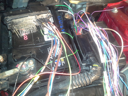
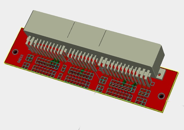
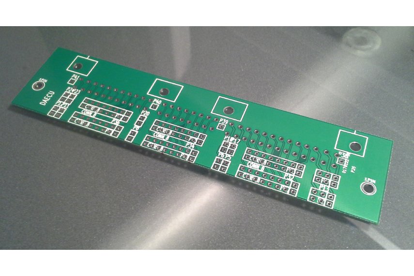
- If you have a connector that has a breakout PCB board for it, you probably want to obtain the breakout PCB for that harness connector. If not, you can simply solder wires directly to the connector, similarly to this forum post.
- It will likely be helpful to get a partial harness from a junkyard, and switch to rusEFI circuit-by-circuit.
- Use junkyard harness to make extension harness. Use the junkyard ECU connector to break out the wire harness to the breakout board. Then from the far side of the breakout board, install the junkyard harness connector. Then connect the original ECU. This should allow you to start and run the engine as normal.
Prepare Engine Wiring
- Connect TPS, MAP, IAT, and other such analog signals to the IO board.
- Connect the 12V system / battery to the IO board connector.
- Calibrate the sensors using TS and Java console as required.
- Crank engine and see whether the RPMs are registering correctly on the Java Console.
- Connect injectors and ignition as required and see if it will start.
Test Engine Wiring
Once connected, you should test the wires. Especially the power wires like coil wires and injector wires. A poor connection with a slight resistance like .1 ohms can cause an electrical fire, which I'm sure you do not want. Once everything is connected, measure both the voltage drop and current from the ECU connector, or wherever is appropriate. Using your voltage and current readings, calculate the resistance, if it's above about .1 ohms, there is an issue. Take note that .1 ohms at 1A is about .1 watt that the connection will have to dissipate. If you have a 12 cylinder, and 12 .1 ohm connections, the connector will have to dissipate 1.2 watts.
Test Outputs
Both rusEFI Console and TS allow you to test whether rusEFI properly controls things like injectors (you would hear the clicks), cooling fan (you would hear it - if needed), fuel pump (you would usually hear it - if needed), ignition coil (that's challenging if you have a distributor).