1995 Honda Accord
ECU pinout
37820-P0A-A51
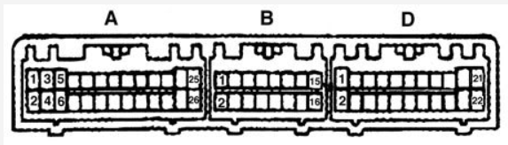
26 pin
| A1 | W63 | BRowN | Injector #1 | Output |
| A2 | W64 | YEL | Injector #4 | Output |
| A3 | W61 | RED | Injector #2 | Output |
| A4 | W62 | GRN/YEL | VTEC Solenoid Valve | Output |
| A5 | W59 | BLUe | Injector #3 | Output |
| A6 | W60 | ORG/BLK | O2 Heater | Output, sink/low |
| A7 | W57 | GRN/BLK | Fuel Pump Relay | Output, sink/low |
| A8 | W58 | * | * | * |
| A9 | W55 | BLK/BLU | Idle Air Control Valve | Output, sink/low. 500Hz |
| A10 | W56 | GRN/WHT | Engine Mount Control | Output |
| A11 | W53 | RED | EGR SOL | Output |
| A12 | W54 | GReeN | Radiator Fan Control Module | Output |
| A13 | W51 | LTGRN/RED | MIL | Output, low-side |
| A14 | W52 | WHT/YEL | Fuel Injection Air Control | |
| A15 | W49 | RED/BLU | A/C compressor clutch relay | Output |
| A16 | W50 | WHT/GRN | Alternator Control | |
| A17 | W47 | * | * | * |
| A18 | W48 | BRN/WHT | FAS (TCM) | |
| A19 | W45 | ORG/GRN | Intake Air Resonator Control Solenoid valve | Output |
| A20 | W46 | RED/YEL | PCS | |
| A21 | W43 | YEL/GRN | Ignition Control Module | Output, \~12v |
| A22 | W44 | * | * | * |
| A23 | W41 | BLK | Power Ground | Ground |
| A24 | W42 | BLK | Power Ground | Ground |
| A25 | W39 | YEL/BLK | Power Source | Input, +12 if ignition is on |
| A26 | W40 | BRN/BLK | Logic Ground | Ground |
16 pin
| B1 | W37 | YEL/BLK | Power Source | Input, constant +12V |
| B2 | W38 | BRN/BLK | Logic Ground | Ground |
| B3 | W35 | WHT/RED | AFS A (TCM) Up/Down shift signal | |
| B4 | W36 | GRN | AFS B (TCM) Up/Down shift signal | |
| B5 | W33 | RED/WHT | AC Pres Switch | |
| B6 | W34 | * | * | * |
| B7 | W31 | lightLTGRN | AT Gear Pos Part/Neutral | Input |
| B8 | W32 | GRN | Power Steering Pres Sw | Input, indicates high power steering load |
| B9 | W29 | BLU RED (or BLK/GRN) | STS | |
| B10 | W30 | ORG | Vehicle Speed Sensor | Input (grounded 4 times per speedometer cable revolution) |
| B11 | W27 | ORanGe | CYP Signal | Input, one pulse per cam rev |
| B12 | W28 | WHT | CYP Ground | |
| B13 | CAM- | ORG BLU | TDC Signal | Input, four pulses per cam revolution |
| B14 | CAM+ | WHT BLU | TDC Ground | |
| B15 | CNK- | BLU GRN | CKP Signal | Input, 24 pulses per cam |
| B16 | CNK+ | BLU YEL | CKP Ground |
22 pin
| D1 | W21 | WHT YEL | Voltage Back Up | Input, constant +12V |
| D2 | W22 | Brake Switch | Input | |
| D3 | W19 | * | * | * |
| D4 | W20 | RED | Service Check Signal | Input, ground to activate |
| D5 | W17 | BLU/WHT | Baro OUT | |
| D6 | W18 | BLU/BLK | VTEC Pressure Switch | Input |
| D7 | W15 | lightLTGRN RED | TXD/RXD data link | |
| D8 | W16 | * | * | * |
| D9 | W13 | WHT RED | ALT FR Signal | |
| D10 | W14 | GRN RED | Electrical Load Detector | Input (signals headlight, radio etc) |
| D11 | W11 | RED/BLK | Throttle Position Sensor | Input |
| D12 | W12 | WHT/BLK | EGR Lift Sensor | Input |
| D13 | W9 | RED/WHT | Engine Coolant Temperature Sensor | Input |
| D14 | W10 | WHT RED | Primary O2 Sensor | Input |
| D15 | W7 | RED YEL | Intake Air Temperature Sensor | Input (bias pull-up 1.5K) |
| D16 | W8 | * | * | * |
| D17 | W5 | WHiTe/YELlow | MAP Sensor | Input: 0.32V @ -13.9 PSI, 4.84V @ 10.94 PSI |
| D18 | W6 | lightLTGRN/BLK | VREF | Output for TCM +5V |
| D19 | W3 | YEL/WHT | VCC1 MAP sensor power supply | Output +5V |
| D20 | W4 | YEL BLU | VCC2 TPS, EGVL sensor power supply | Output +5V |
| D21 | W1 | GRN/WHT | SG1 MAP sensor GND | Ground |
| D22 | W2 | GRN BLU | SG2 - Sensors Ground | ground |
Components
[Honda F22B1 Engine - Wikipedia]](http://en.wikipedia.org/wiki/Honda_F_engine#F22B1)
Fuel Injector 06164-P0A-A00 248cc/min Low impedance
MAP sensor 37830-P05-A01
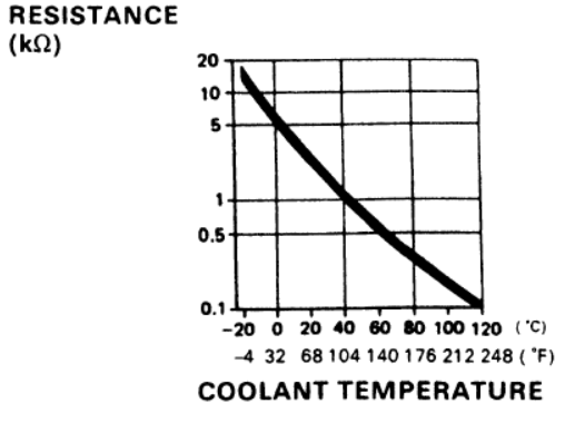
ECT sensor 37870-PJ7-003
IAT 37880-P0A-A02
DISTRIBUTOR ASSY D4T92-04
ignition control module 30120-P0A-A01
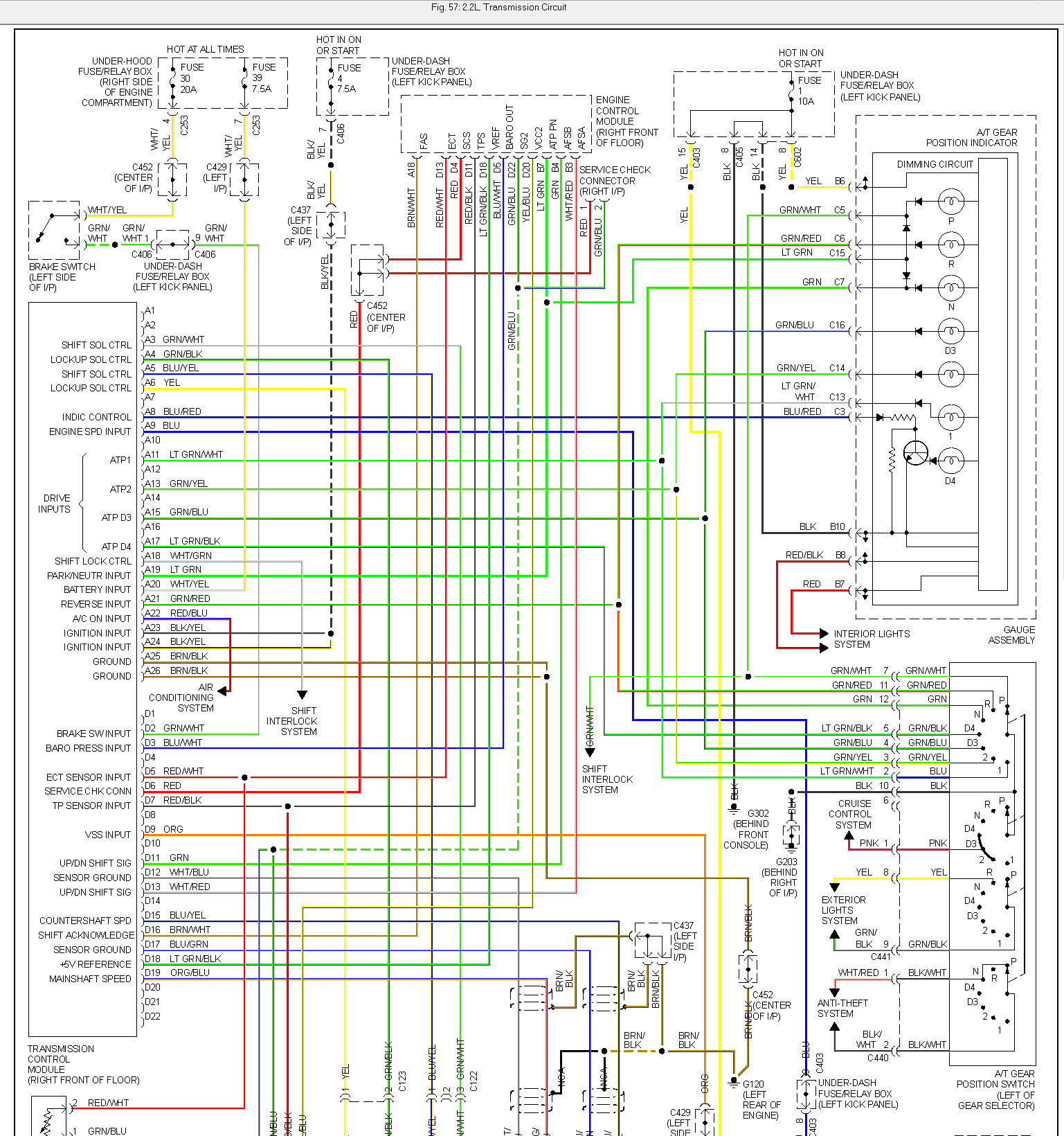
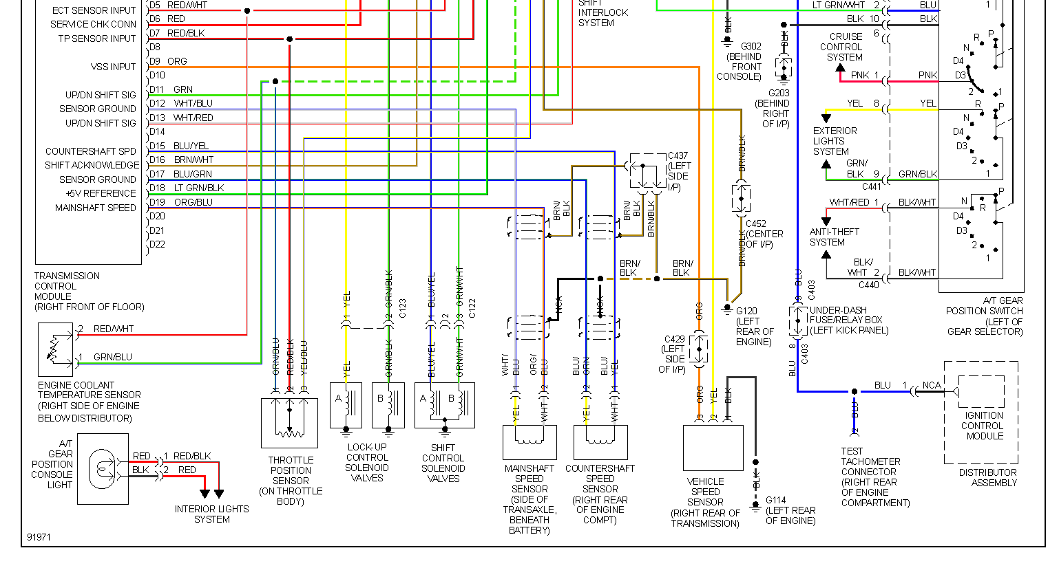
TCM pinout
tcm 28100-P0H-A02
TCM 26 pin
| A1 | * | * | * |
| A2 | * | * | * |
| A3 | GRN/WHT | Shift solenoid control B | Output |
| A4 | GRN/YEL | Lockup solenoid B | Output |
| A5 | BLU/YEL | Shift solenoid control A | Output |
| A6 | YELlow | Lockup solenoid A | Output |
| A7 | * | * | * |
| A8 | D4 light control | Output | |
| A9 | BLUe | Engine Speed from dizzy | Input |
| A10 | * | * | * |
| A11 | Selector "1" input | ||
| A12 | * | * | * |
| A13 | Selector "2" input | ||
| A14 | * | * | * |
| A15 | Selector "D3" input | ||
| A16 | * | * | * |
| A17 | Lt GRN/BLacK | Selector "D4" input | |
| A18 | WHT/GRN | Shift lock control | |
| A19 | Lt GRN | Park/Neutr input | |
| A20 | WHT/YEL | Battery input | |
| A21 | Reverse input | Input | |
| A22 | A/C on input | Input | |
| A23 | Ignition input | ||
| A24 | Ignition input | ||
| A25 | BRN/BLK | Ground | Ground |
| A26 | BRN/BLK | Ground | Ground |
TCM 22 pin
| D1 | * | * | * |
| D2 | * | Brake switch | Input |
| D3 | Baro Pressure | Input | |
| D4 | * | * | * |
| D5 | Engine Coolant Temp sensor | Input | |
| D6 | Service Check Conn | ||
| D7 | Throttle Position Sensor | Input | |
| D8 | * | * | * |
| D9 | ORG | Vehicle Speed Sensor | Input |
| D10 | * | * | * |
| D11 | GRN | Up/Down shift sig | |
| D12 | Mainshaft speed Sensor Ground | Ground | |
| D13 | WHT/RED | Up/Down shift sig | |
| D14 | * | * | * |
| D15 | Countershaft speed | Input | |
| D16 | BRN/WHiTe | Shift Ack | |
| D17 | Countershaft speed Sensor Ground | Ground | |
| D18 | LT GRN/BLK | Voltage Reference | Input +5 |
| D19 | Mainshaft speed | Input | |
| D20 | * | * | * |
| D21 | * | * | * |
| D22 | * | * | * |
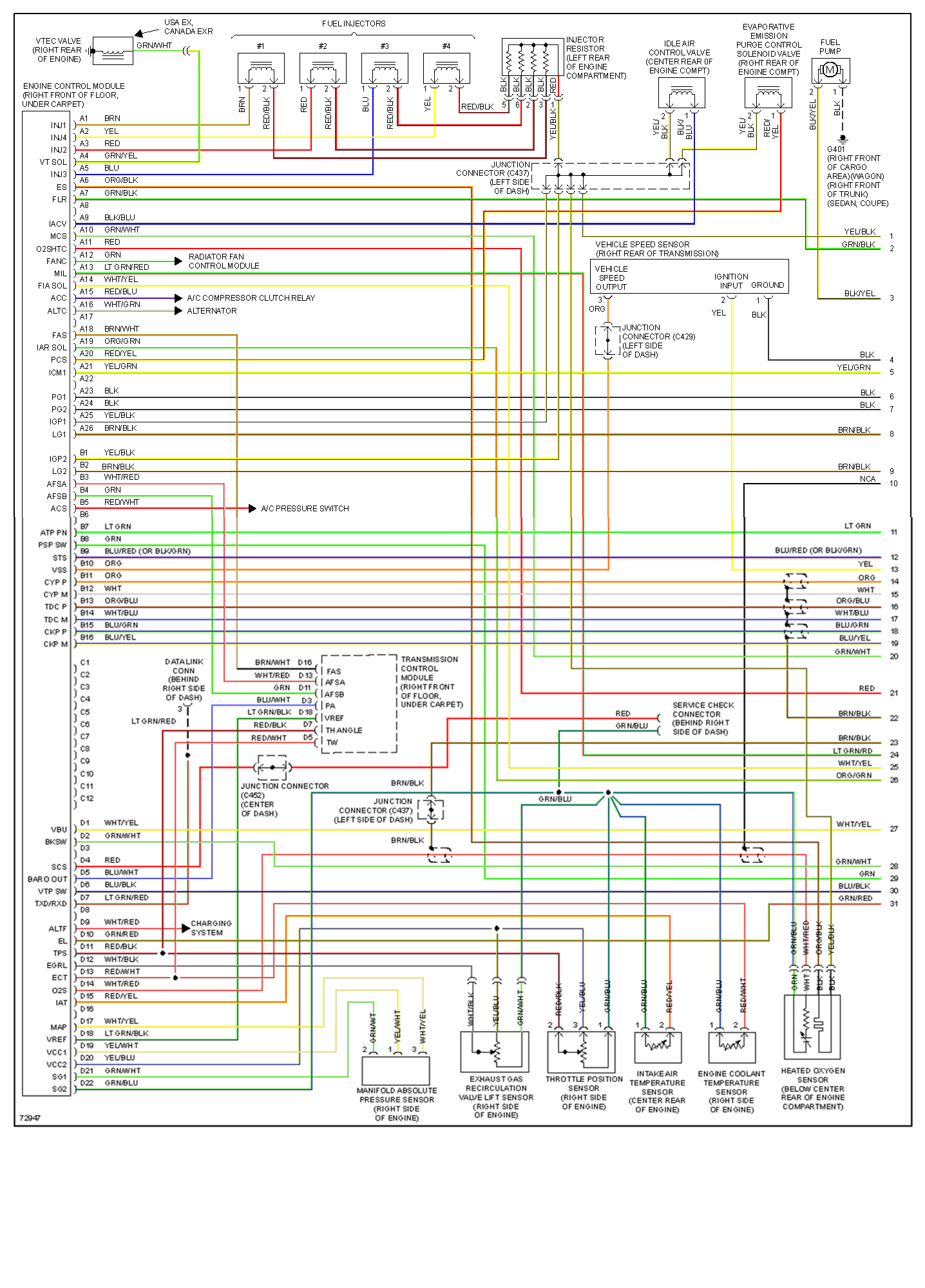
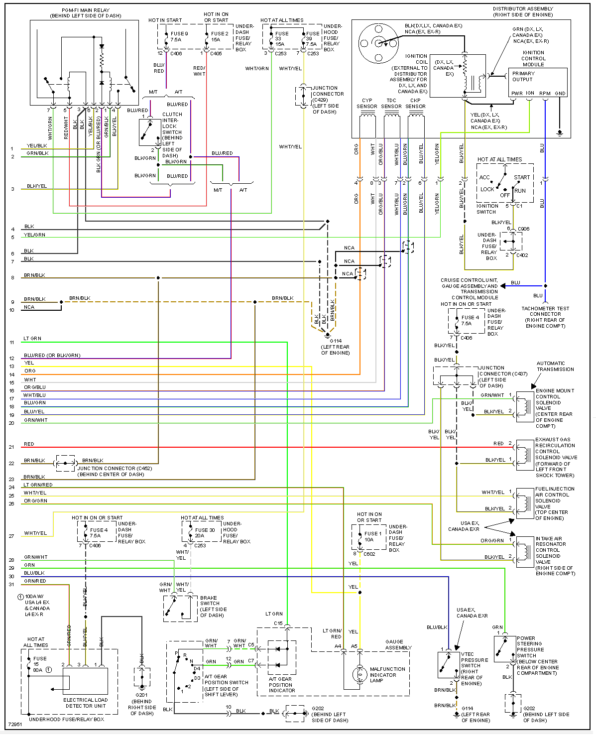
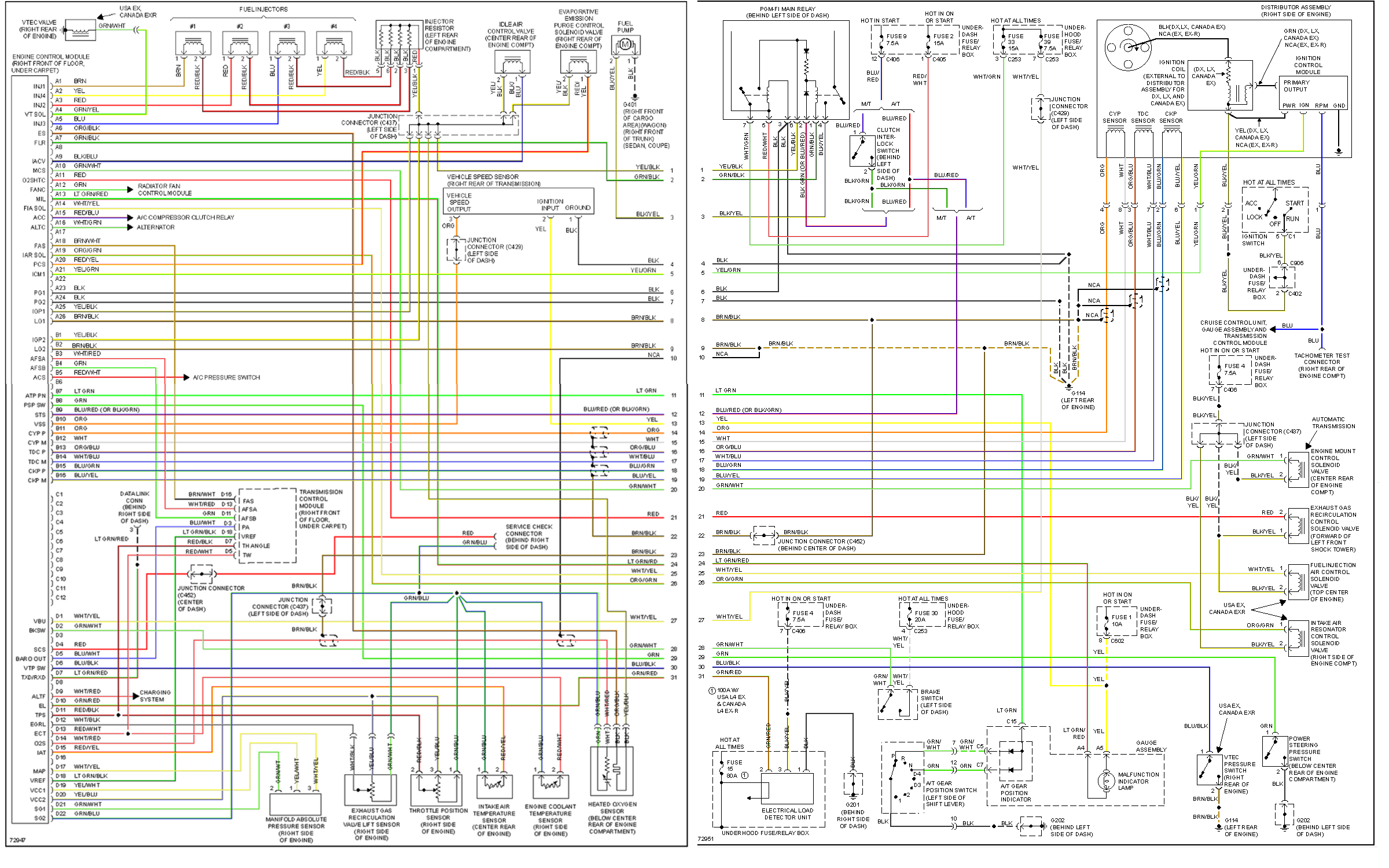
diagram
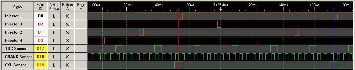
trigger signal
Measured 845 ohms between pins B15 / B16 also same for B14 / B13 and same for B12 / 11.
stock ECU schematics highlights
IC1: main chip, OKI 66911, DIP
Inputs: TDC input: HIC1#10, TTL signal: HIC1##8, goes to IC7#35
CYP input: HIC1#15, TTL signal: HIC1##12, goes to IC1#27
CKP input: HIC1#19, TTL signal: HIC1##17, goes to IC1#34
Outputs: Ignition module: IC7#28 via R28 & Q22
See also Honda Prelude 1993